云计算 阅读材料 15 Case Studies - Distributed File Systems
本页目录
In this module, we discuss two distributed file systems: the Hadoop Distributed File System (HDFS) and Ceph FS.
Both HDFS and Ceph FS are designed to be big-data file systems, but have subtle differences. HDFS is designed for large files following a write-once, read-many semantic. Ceph FS, on the other hand is geared towards being a general-purpose distributed file system that can be used for a variety of applications deployed on a virtualized cluster. Ceph FS is a file system layered on top of a distributed object store. This module elaborates on some of the design choices made by the developers of these file systems for their target applications.
As a recap, a distributed file system (DFS) is a file system that has files distributed among multiple file servers. It is important to note that in a distributed file system, the client views a single, global namespace that encompasses all the files across all the file system servers. DFSs require metadata management so that clients can locate the required files and file blocks across the file servers. DFSs are typically deployed on multiple file-sharing nodes and are intended for use by multiple users at the same time. As with any shared resource, multiple design considerations must be considered: Performance, consistency, fault tolerance, availability are some of them.
Origins and Evolution of Distributed File Systems
File systems have largely been influenced by the UNIX file system and BSD's Fast File System (FFS), which were used as local file systems. Recall that the primary focus of these file systems is to organize data on disk in a manner that is fast and reliable.
Networked file systems such as NFS have since emerged in order to allow users to share files over a network. NFS uses a client-server architecture, where a server can share the data that it holds to a number of clients. It is a simple protocol that continues to be used to this day for sharing files over a network. Files cannot be distributed across multiple servers in a coordinated fashion in NFS, each server can simply share a number of files. There is no consistent global view of the namespace, either. Clients can mount NFS shares anywhere within their local file system tree. Hence, this approach is limited in its ability to scale to thousands of clients/servers, and is limited to use in local area networks (LANs).
Andrew File System (AFS) is an early example of a true distributed file system. AFS enables cooperating hosts (clients and servers) to efficiently share file system resources across both local area and wide area networks. AFS consists of cells, an administrative grouping of servers that present a single cohesive file system. Cells can be combined to form a single global namespace. Any client that accesses data from AFS will first copy the file locally to the client. Changes to the file will be made locally as long as the file is open. When the file is closed, the AFS client will sync the changes back to the server. An evolution of AFS is CODA, which is a distributed file system that improves on AFS, particularly with respect to sharing semantics and replication. Both AFS and CODA are POSIX compliant, which means that they work with existing UNIX applications without any modifications.
In 2003, Google revealed the design of its distributed file system, called GFS [2] , which was designed from scratch to provide efficient, reliable access to data using large clusters of commodity hardware. GFS is designed to store very large files as chunks stored on multiple servers (typically of size 64MB), in a replicated fashion. Although GFS has a singular client view like AFS, the location of file chunks is exposed to the user, given opportunities to fetch files from the closest available replica. GFS, however, is not POSIX compliant, which means that applications have to use an special API to work with GFS. The Hadoop Distributed File System (HDFS), is an open-source variant of GFS, which we will explore in detail in this module.
In 2006, Ceph was first described in a paper by Weil et.al [1] . Ceph is designed to be a distributed object storage service that can be scaled to hundreds of thousands of machines, while storing petabytes of data. Applications then talk to Ceph through various APIs, ranging from a native API that is similar to the way GFS works, to a POSIX-compliant file system API called Ceph FS. Ceph also supports a block device abstraction, which makes it a file system that is suitable for storing virtual machine images.
This domain is changing quite fast. Google has evolved GFS into a system known as Colossus [3] . Although details are sketchy, it appears that Google has moved away from GFS's design of a single metadata master and instead use multiple metadata servers. It also appears that they have moved away from simple replication to a scheme based on Reed-Solomon encoding to ensure that data is recoverable in case of failures.
The Hadoop Distributed File System (HDFS)
HDFS
Google's MapReduce programming model allows computational jobs to be structured in terms of two functions: map and reduce. Input is fed into MapReduce as key-value pairs, where it is then processed through a map function and fed into a reduce function. The reduce operation then produces a result, which is also in the form of key-value pairs. MapReduce is designed to execute many instances of map and reduce operations in parallel over a large computational cluster. The MapReduce programming model is covered in detail in the next unit of this course.
The MapReduce programming model assumes the availability of a distributed storage system that is available across all the nodes of the cluster, with a single namespace, which is where Google File System (GFS) [1] comes in. GFS is a distributed file system (DFS) that is collocated with the nodes of the MapReduce cluster. GFS is designed to work in tandem with MapReduce and maintains a single namespace for the entire MapReduce cluster.
Video 4.12: Hadoop Distributed File System
Both Google's MapReduce and GFS implementations remain proprietary. However, an open-source clone of MapReduce, called Apache Hadoop, [2] has emerged and gained popularity in big-data circles. HDFS is an open-source clone of GFS. HDFS is designed to be a distributed, scalable, fault-tolerant file system that primarily caters to the needs of the MapReduce programming model. Video 4.12 introduces HDFS.
It is important to note that HDFS is not POSIX-compliant and is not a mountable file system on its own. HDFS is typically accessed via HDFS clients or by using application programming interface (API) calls from the Hadoop libraries. However, the development of a File system in User SpacE (FUSE) driver for (HDFS) allows it to be mounted as a virtual device in UNIX-like operating systems.
HDFS Architecture
As described earlier, HDFS is a DFS that is designed to run on a cluster of nodes and is architected with the following goals:
- A single, common, cluster-wide namespace
- Ability to store large files (e.g. terabytes or petabytes)
- Support for the MapReduce programming model
- Streaming data access for write-once, read-many data access patterns
- High availability using commodity hardware
An HDFS cluster is illustrated in Figure 4.25.
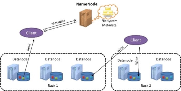
HDFS follows a master-slave design. The master node is called the NameNode. The NameNode handles the metadata management for the entire cluster and maintains a single namespace for all the files stored on HDFS. The slave nodes are known as DataNodes. The DataNodes store the actual data blocks on the local file system within each node.
Files in HDFS are split into blocks (also called chunks), with a default size of 128MB each. In contrast, local file systems typically have block sizes of about 4KB. HDFS uses large block sizes because it is designed to store extremely large files in a manner that is efficient to process with MapReduce jobs.
A single map task in MapReduce is configured by default to work on a single HDFS block independently, and hence multiple map tasks can process multiple HDFS blocks in parallel. If the block size is too small, a large number of map tasks will need to be distributed across the nodes of the cluster, and the overhead of doing so might negatively impact performance. On the other hand, if the block is too large, the number of map tasks that can process the file in parallel is reduced, thereby affecting parallelism. HDFS allows block sizes to be specified on a per-file basis, so users can tune the block size to achieve the level of parallelism they desire. MapReduce's interaction with HDFS is discussed in detail in Unit 5.
In addition, because HDFS is designed to tolerate failures of individual nodes, data blocks are replicated across nodes to provide data redundancy. This process is elaborated in the following sections.
Cluster Topology in HDFS
Hadoop clusters are typically deployed in a data center that consists of multiple racks of servers connected using a fat-tree topology (as discussed in Unit 2). To this end, HDFS has been designed with cluster-topology awareness, which aids in making block-placement decisions to influence performance and fault tolerance. Common Hadoop clusters have about 30 to 40 servers per rack, with a gigabit switch dedicated to the rack and an uplink to a core switch or router, which has bandwidth that is shared among many racks in the data center (Figure 4.26).
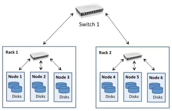
The salient point to note is that Hadoop assumes that the aggregate bandwidth within the nodes in a rack is higher than the aggregate bandwidth across nodes on different racks. This assumption is engineered into the design of Hadoop when it comes to data access and replica placement (which is discussed in the following sections).
When HDFS is deployed on a cluster, system administrators can configure it with a topology description that maps each node to a particular rack in the cluster. The network distance is measured in hops, where one hop corresponds to one link in the topology. Hadoop assumes a tree-style topology, and the distance between two nodes is the sum of their distances to their closest common ancestor.
In the example in Figure 4.26, the distance between Node 1 and itself is zero hops (the case when two processes are communicating on the same node). The distance between Node 1 and Node 2 is two hops, while the distance between Node 3 and Node 4 is four hops.
Video 4.13 walks through file read and write operations in HDFS.
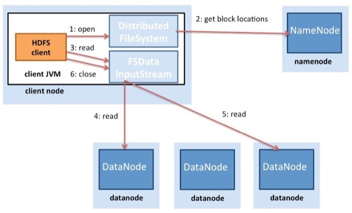
Figure 4.27 illustrates the process of a file read in HDFS. An HDFS client (the entity that needs to access a file) first contacts the NameNode when a file is opened for reading. The NameNode then provides the client with a list of block locations of the file. Hadoop also assumes that blocks are replicated across nodes, so the NameNode actually finds the closest block to the client when providing the location of a particular block. The locality is determined in the following order (of decreasing locality): blocks within the same node as the client, blocks in the same rack as the client, and blocks that are off rack to the client.
Once the block locations are determined, the client opens a direct connection to each DataNode and streams the data from the DataNode to the client process, which is done when the HDFS client invokes the read operation on the data block. Hence, the block does not have to be transferred in its entirety before the client can begin computation, thereby interleaving computation and communication. Once the client has finished reading the first block, it repeats this process with the remaining blocks until the client has finished reading all of the blocks and then proceeds to close the file.
It is important to note that clients contact the DataNode directly to retrieve data. This contact allows HDFS to scale to a large number of concurrent clients for simultaneous, parallel reads of data.
File writes are different from file reads in HDFS (Figure 4.28). A client that needs to write data to HDFS first contacts the NameNode and then notifies it of a file creation. The NameNode checks whether the file already exists and verifies whether the client has permission to create a file. If the checks pass, the NameNode then makes a record of a new file.
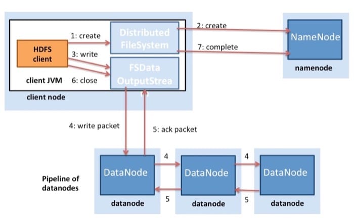
The client then proceeds to write the file to an internal data queue and requests the NameNode for block locations on DataNodes on the cluster. Blocks on the internal queue are then transferred to individual DataNodes in a pipelined fashion. The block is written on the first DataNode, which then pipelines the block to other DataNodes in order to write replicas of the block. Thus the blocks are replicated during the file write itself. It is important to note that HDFS does not acknowledge a write to the client (step 5 in Figure 4.28) until all the replicas for that file have been written by the DataNodes.
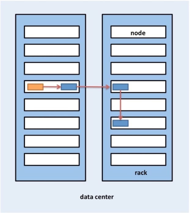
Hadoop also uses the notion of rack locality during replica placement. Data blocks are triple replicated in HDFS by default. HDFS attempts to place the first replica on the same node as the client that is writing the block. In case a client process is not running in the HDFS cluster, a node is chosen at random. The second replica is written to a node that is on a different rack from the first (off rack). The third replica of the block is then written to another random node on the same rack as the second. Further replicas are written to random nodes in the cluster, but the system tries to avoid placing too many replicas on the same rack. Figure 4.29 illustrates the replica placement for a triple-replicated block in HDFS. The idea behind HDFS's replica placement is to be able to tolerate node and rack failures. For example, when an entire rack goes offline due to power or networking problems, the requested block can still be located at a different rack.
Synchronization: Semantics
HDFS's semantics have changed a bit. Early versions of HDFS followed strict immutable semantics. Once a file was written in the earlier versions of HDFS, it could never again be re-opened for writes. Files could still be deleted. However, current versions of HDFS support appends in a limited manner. This is still quite limited in the sense that existing binary data once written to HDFS cannot be modified in place.
This design choice in HDFS was made because some of the most common MapReduce workloads follow the write once, read many data-access pattern. MapReduce is a restricted computational model with predefined stages, and outputs of reducers in MapReduce write independent files to HDFS as output. HDFS focuses on simultaneous, fast read accesses for multiple clients at a time.
Consistency Model
HDFS is a strongly consistent file system. Each data block is replicated to multiple nodes, but a write is declared to be successful only after all the replicas have been written successfully. Hence all clients should see the file as soon as the file is written, and the view of the file across all the clients will be the same. The immutable semantics of HDFS make this comparatively easy to implement because a file can be opened for writing only once during its lifetime.
Fault Tolerance in HDFS
The primary fault-tolerance mechanism in HDFS is replication. As pointed out earlier, by default, every block written to HDFS is replicated three times, but this can be changed by the users on a per-file basis, if needed.
The NameNode keeps track of DataNodes through a heartbeat mechanism. Each DataNode sends periodic heartbeat messages (every few seconds) to the NameNode. If a DataNode dies, then the heartbeats to the NameNode are stopped. The NameNode detects that a DataNode has died if the number of missed heartbeat messages reaches a certain threshold. The NameNode then marks the DataNode as dead and will no longer forward any I/O requests to that DataNode. The blocks stored on that DataNode should have additional replicas on other DataNodes. In addition, the NameNode does a status check on the file system to discover under-replicated blocks and performs a cluster rebalance process to initiate replication for the blocks that have less than the desired number of replicas.
The NameNode is a single point of failure (SPOF) in HDFS because a failure of the NameNode will bring the entire file system down. Internally, the NameNode maintains two on-disk data structures that store the state of the file system: an image file and an edit log. The image file is a checkpoint of the file system metadata at some point in time, while the edit log is a log of all of the transactions of the file system metadata since the image file was last created. All incoming changes to the file system metadata are written to the edit log. At periodic intervals, the edit logs and image file are merged to create a new image file snapshot, and the edit log is cleared out. On a NameNode failure, however, the metadata would be unavailable, and a disk failure on the NameNode would be catastrophic because the file metadata would be lost.
To back up the metadata on the NameNode, HDFS allows for the creation of a secondary NameNode, which periodically copies the image files from the NameNode. These copies will help in recovering the file system in the event of data loss on the NameNode, but the final few changes that were in the edit log of the NameNode would be lost. Ongoing work in the latest versions of Hadoop aims at creating a true over-abundant, secondary NameNode that would automatically take over when the NameNode fails.
HDFS in Practice
Although HDFS was primarily designed to support Hadoop MapReduce jobs by providing a DFS for map and reduce operations, HDFS has found a myriad of uses with big-data tools.
HDFS is used in several Apache projects that build on top of the Hadoop framework, including Pig, Hive, HBase, and Giraph. HDFS support is also included in other projects, such as GraphLab.
The primary advantages of HDFS include the following:
- High bandwidth for MapReduce workloads: Large Hadoop clusters (thousands of machines) are known to continuously write up to 1 terabyte per second using HDFS.
- High reliability: Fault tolerance is a primary design goal in HDFS. HDFS replication provides high reliability and availability, particularly in large clusters, in which the probability of disk and server failures increase significantly.
- Low costs per byte: When compared to a dedicated, shared-disk solution, such as a SAN, HDFS costs less per gigabyte because storage is collocated with compute servers. With SAN, you have to pay additional costs for managed infrastructure, such as the disk array enclosure and higher-grade enterprise disks, to manage failures in hardware. HDFS is designed to run with commodity hardware, and redundancy is managed in software to tolerate failures.
- Scalability: HDFS allows DataNodes to be added to a running cluster and offers tools to manually rebalance the data blocks when cluster nodes are added, which can be done without shutting the file system down.
The primary disadvantages of HDFS include the following:
- Small file inefficiencies: HDFS is designed to be used with large block sizes (64MB and larger). It is meant to take large files (hundreds of megabytes, gigabytes, or terabytes) and chunk them into blocks, which can then be fed into MapReduce jobs for parallel processing. HDFS is inefficient when the actual file sizes are small (in the kilobyte range). Having a large number of small files places additional stress on the NameNode, which has to maintain metadata for all the files in the file system. Typically, HDFS users combine many small files into larger ones using techniques such as sequence files.
- POSIX non-compliance: HDFS was not designed to be a POSIX-compliant, mountable file system; applications will have to be either written from scratch or modified to use an HDFS client. Workarounds exist that enable HDFS to be mounted using a FUSE driver, but the file system semantics do not allow writes to files once they have been closed.
- Write-once model: The write-once model is a potential drawback for applications that require concurrent write accesses to the same file. However, the latest version of HDFS now supports file appends.
In short, HDFS is a good option as a storage back end for distributed applications that follow the MapReduce model or have been specifically written to use HDFS. HDFS can be used efficiently with a small number of large files rather than a large number of small files.
References
- Ghemawat, Sanjay, Gobioff, Howard, and Leung, Shun-Tak (October 2003). "19th Symposium on Operating Systems Principles (conference), Lake George, NY." The Google File System.
- White, Tom (2012). Hadoop: The Definitive Guide. O'Reilly Media, Yahoo Press.
Ceph FS
Ceph
Ceph is a storage system that can be deployed on large clusters of servers with attached disks. Video 4.14 covers the basic concepts behind Ceph.
The design goals for Ceph [2] include the following:
- General-purpose storage cluster which is flexible to support a wide range of applications.
- An architecture that can seamlessly scale to hundreds of thousands of nodes and petabytes of storage.
- Highly reliable system without any single point of failure, that is self-managing and robust.
- The system must run on readily-available commodity hardware.
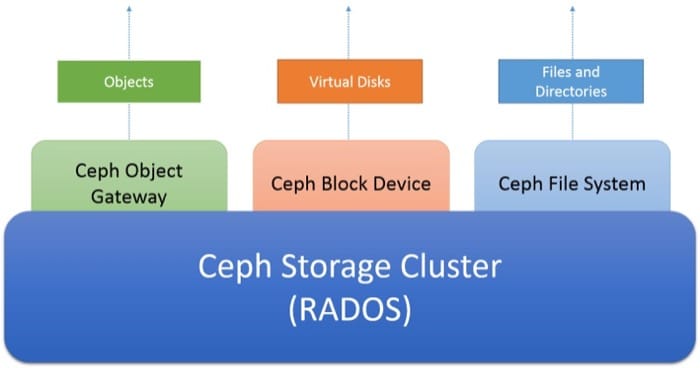
Ceph is designed to be accessible through 3 different abstractions, as shown in Figure 4.30 below:
The Ceph storage cluster is a distributed object store. Layered on top of the storage cluster are different client-facing storage services. The Ceph object gateway service allows for clients to access a Ceph storage cluster using a REST-based HTTP interface that is compatible with Amazon's S3 and Openstack Swift protocols. The Ceph block device service allows for clients to access the storage cluster as block devices, which can be formatted with a local file system and mounted in an operating system, or used as a virtual disk to operate virtual machines in Xen, KVM, VMWare or QEMU. Finally, the Ceph file system (Ceph FS) provides the file and directory abstraction over the entire storage cluster as a POSIX-compliant file system.
Taking a deeper look, the Architecture of Ceph are illustrated below (Figure 4.31):
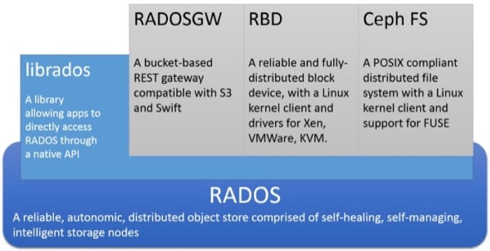
At the heart of Ceph is a distributed object storage system called RADOS. Clients can interact with RADOS directly using a low level API called librados, which is socket-based and supports a number of programming languages. Alternatively, clients can interact with the 3 higher level APIs that provide 3 separate abstractions into RADOS.
RADOS Gateway or radosgw allows for clients to access RADOS through a REST-based gateway over HTTP. This emulates the Amazon S3 object service and is compatible with applications that use the Amazon S3 API or the Openstack SWIFT API.
RADOS Block Device or RBD exposes the RADOS object store as a general-purpose distributed block device, much like a SAN. RBD allows for block devices to be carved out from RADOS and mounted on Linux systems using a kernel driver. RBDs can also be used as virtual disk images for popular virtualization systems such as Xen, VMWare, KVM and QEMU.
Ceph FS is a POSIX compliant distributed file system layered over RADOS which can be directly mounted within the file systems of Linux clients. Ceph FS will be discussed in detail later on this page.
Ceph Storage Cluster Architecture (RADOS)
At the heart of Ceph is the Reliable, Autonomous, Distributed Object Store (RADOS). In RADOS, data is stored as objects distributed over a cluster of machines. Clients interact with a RADOS cluster by storing and retrieving objects. An object consists of an object name (which is the key used to identify an object), as well as the binary contents of the object (which is the value associated with a particular object key). The role of RADOS is to store objects in a distributed fashion across a cluster in a scalable, reliable and fault-tolerant manner.
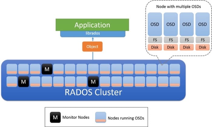
There are two types of nodes in a RADOS cluster: object storage daemons (OSDs) and monitor nodes (Figure 4.32). An OSD stores objects and responds to requests for objects. OSDs stores these objects on nodes using the local file system on each node, and keep a buffer cache to improve performance. Monitor nodes keep a watch on the status of the cluster to keep track of OSDs that are entering and leaving the cluster.
Cluster State and Monitors in RADOS
The state of a RADOS cluster is encapsulated into an object known as the cluster map, which is shared by all the nodes in a cluster. The cluster map contains information about the state of a cluster at any given moment, including the number of OSDs that are currently present, a compact representation of how the data is distributed among the OSDs (which will be discussed in detail in the next section), and a logical timestamp denoting the time that this cluster map was built. Updates to the cluster map are done in a peer-to-peer, incremental fashion by the monitor nodes. This means that only the changes in the cluster map from one timestamp to another are communicated between the nodes in a cluster, to keep the amount of data transferred between nodes small.
The monitors in RADOS are collectively responsible for the management of the storage system by storing the master copy of the cluster map and sending out periodic updates in case there is a change in the state of the OSDs. The monitors are organized based on the paxos algorithm, and requires a majority of the monitors to read or update the cluster map. The monitors ensure that the map updates are serialized and consistent. A RADOS cluster is designed to have a small number of monitors (>3) and is typically an odd number to ensure that there are no ties to break when individual monitors have to come to a consensus.
Data Placement in RADOS
For a distributed object storage to work correctly, a client must be able to contact the correct OSD to interact with an object. First, a client contacts a Monitor to retrieve the cluster map for the given storage cluster. The information contained in the cluster map can be used to determine the exact OSD responsible for a particular object in the cluster.
The first step is to determine the placement group of a particular object (Figure 4.33). A placement group can be thought of as a bucket in which an object resides. This is done by using a hash function (the latest hash function to be used is always obtained from the cluster map). Once a placement group for the given object is determined, the client then needs to find the OSD that is responsible for that placement group.
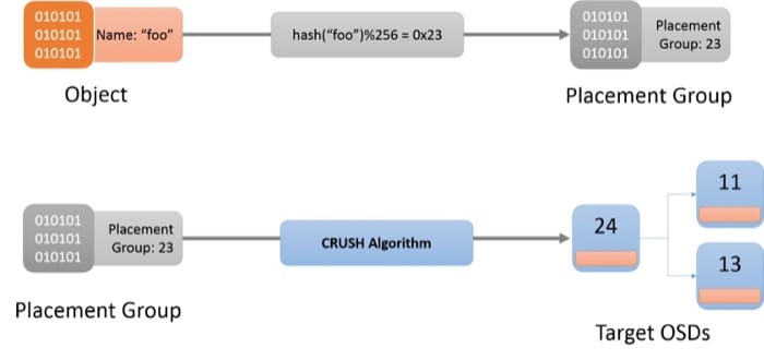
The algorithm used to assign placement groups to OSDs is known as the Controlled Replication Under Scalable Hashing (CRUSH) [1] algorithm (Figure 4.33). CRUSH assigns placement groups across a cluster in a pseudo-random, but deterministic manner. CRUSH is more stable than a hash function, in the sense that when OSDs enter or leave the cluster, CRUSH ensures that most placement groups remain where they are and shifts only a small amount of data to maintain a balanced distribution. A simple hash function, on the other hand would require redistribution of a majority of keys when buckets are added or removed. The entire description of the CRUSH algorithm is beyond the scope of this discussion, interested readers should refer to [1] .
When an object name is hashed to a placement group, CRUSH produces a list of exactly r OSDs that are responsible for the placement group. Here, r is the number of replicas for a given object. Based on the information in the cluster map, the active OSDs that are in this mapping are identified, and then that OSD can be contacted to interact (operations such as create, read, update, delete) with the specified object.
Replication in RADOS
In RADOS, an object is replicated among multiple OSDs that are associated with that object's placement group. This ensures that there are multiple copies of a particular object in case a certain OSD fails. RADOS has multiple available schemes in which the replication is actually performed; these are the primary copy, chain, and splay replication schemes (Figure 4.34).
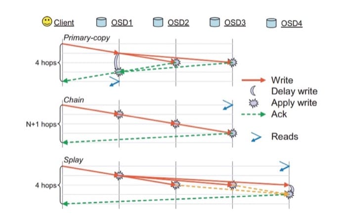
Primary Copy Replication: In the primary copy replication scheme, a client interacts with the first available OSD (the primary replica OSD) to interact with an object. The primary replica OSD will process the request and respond back to the client. In case of a write, the primary replica OSD will forward the write request to r-1 replicas which will then update their local copies of the object and respond to the master. The write operation on the master is delayed until all the writes are committed by the other OSDs for that object. The master will then acknowledge the write to the client. The write is not complete until all the replicas have responded to the primary copy OSD. The same process applies for reads, the primary copy will respond to a read only after all replicas have been contacted and the object value is the same across all replicas.
Chain Replication: Requests for an object are forwarded down the chain until the rth (final) replica is found. If the operation is a write, it will be committed to each of the replicas on the way to the last replica. The final OSD containing the final replica will finally acknowledge the write to the client. Any read operation will be directed straight to the tail, in order to reduce the number of hops that are required to read the data from a cluster.
Splay Replication: Splay replication combines elements of both primary copy replication and chain replication. Read requests are directed to the last OSD in the replica chain, while writes are first sent to the head. Unlike chain, the updates to the middle OSDs are done in parallel, similar to the primary copy replication scheme.
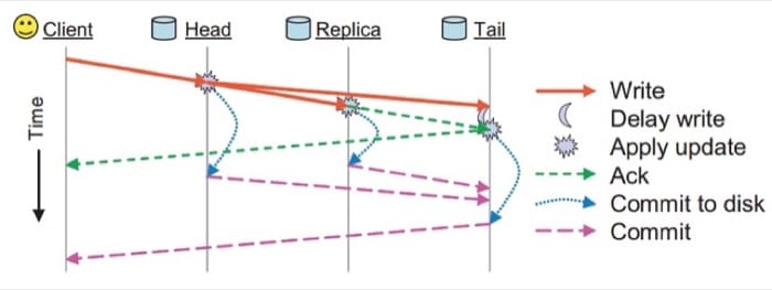
In addition to these replication schemes, persistence in RADOS is handled by utilizing two separate acknowledgement messages (Figure 4.35). Each OSD has a buffer cache of the data served by it. Updates are written to the buffer cache and acknowledged back immediately through an ack message. This buffer cache is periodically flushed to disk, and when the last replica has committed the data to disk, a commit message is sent to the client, indicating that the data has been persisted.
Consistency Model in RADOS
Every message in RADOS (both from the client as well as peer-to-peer messages among nodes) are tagged with the timestamp to ensure that the messages are ordered and applied in a consistent fashion. If OSDs detect a wrong message due to an out-of-date cluster map from the message requester, it will send the incremental map updates to bring the message requester up to date.
There are corner cases in which strict consistency guarantees offered by RADOS must be carefully handled. If the placement group mappings for a particular OSD changes (in the event of a change in the cluster map), then the system must ensure that the hand-off of the placement groups between the old OSDs and the new OSDs should be done in a seamless and consistent manner. During a placement group change, new OSDs are required to contact the old OSDs for the state handover, during which the old OSDs will learn of the change and stop responding to queries for those particular placement groups.
Another case where strict consistency guarantees may be difficult to achieve is in the event of a network failure that causes a network partition. In this case some clients that have an old cluster map may continue to perform read operations on that OSD while an updated map may change the OSD responsible for that placement group. Recall that this is a failure scenario that was previously highlighted in our discussion of the CAP theorem. This inconsistency window will always exist in this case. RADOS seeks to mitigate the effect of this scenario by requiring all OSDs to heartbeat with other replicas at a default interval of 2 seconds. If a particular OSD cannot reach the other replica groups in a certain threshold, it will block its reads. In addition, OSDs that are assigned to be the new primary for a particular placement group should either receive an acknowledgement of the handover from the old placement group primary or wait for the heartbeat interval to assume that the old placement group primary is down. This way, the potential inconsistency window in a RADOS cluster in the presence of network partitions is reduced.
Failure Detection and Fault Tolerance in RADOS
Node failures in RADOS are detected during a failure of communication between OSDs assigned to a placement group or between OSDs and monitor nodes. If a node fails to respond within a limited number of reconnect attempts, it is declared as dead. OSDs that are part of a placement group will exchange heartbeat messages to ensure that failures are detected. This results in the monitor nodes taking the lead in updating the cluster map and notifying all nodes through an incremental map update message. Following an update of the cluster map, OSDs will exchange objects between themselves to ensure that the desired number of replicas are maintained for each placement group. If an OSD discovers through a message that it has been declared dead, it will simply sync its buffer to disk and kill itself to ensure that the behavior is consistent.
Ceph FS
As indicated in Figure 4.31 above, the Ceph FS is a layer of abstraction over the RADOS storage system. RADOS does not have any notion of metadata for an object apart from object name. The Ceph file system allows for file metadata to be layered on top of individual file objects stored in RADOS. Video 4.15 explains teh concept of CephFS.
In addition to the cluster node roles of OSDs and Monitors, Ceph FS introduces metadata (MDS) servers (Figure 4.36). These servers store the file system metadata (the directory tree, as well as the access control lists and permissions, mode, ownership information, and timestamps for each file).
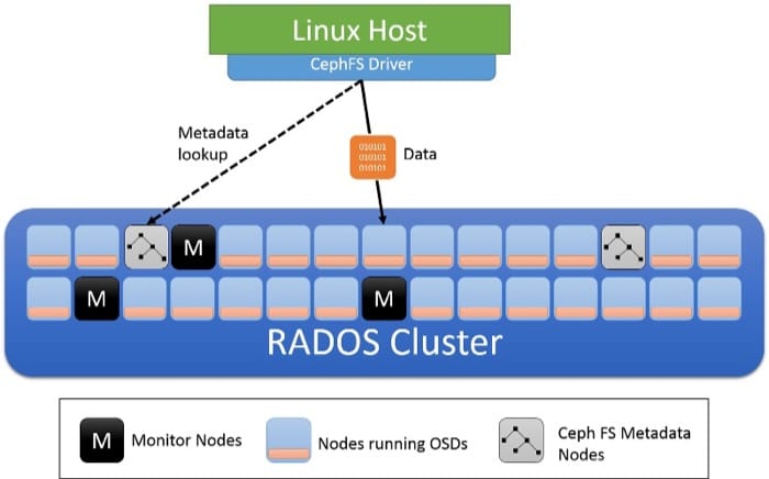
The metadata used by Ceph FS differs from the metadata used by local file system in a number of ways. Recall that in a local file system a file is described by an inode, which contains a list of pointers pointing to the data blocks of a file. Directories in a local file system are simply special files which have links to other inodes which may be other directories or files. In Ceph FS, a directory object in the metadata server contains all the inodes embedded inside it.
Dynamic Subtree Partitioning
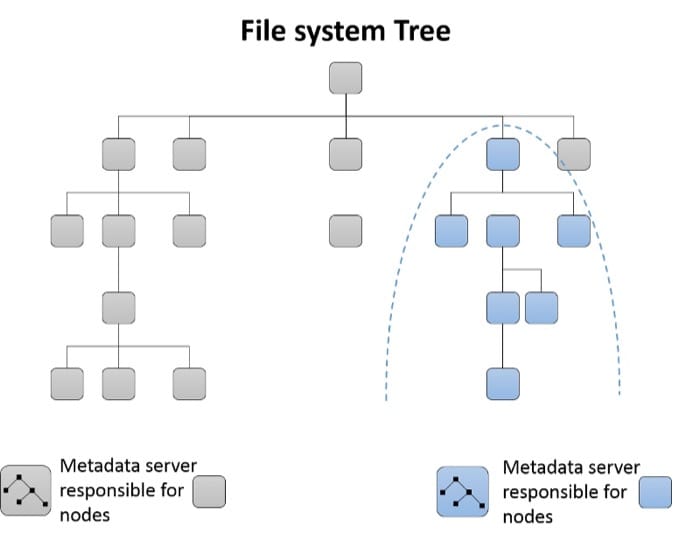
Initially a single metadata server will be responsible for the entire metadata for the cluster. As metadata servers are added to the cluster, the directory tree of the file system is partitioned and assigned to the resulting group of metadata servers (Figure 4.37). Each MDS measures the popularity of metadata within its directory hierarchy using counters. A weighted scheme [3] is used to not only update the counter of a specific leaf node in the directory, but also for the ancestors of that directory element up to the root. Thus each MDS is able to keep a list of hotspots in the metadata that can be moved off to a new MDS when it's added to the cluster.
Caching and Fault Tolerance in Metadata servers
Metadata servers in Ceph FS typically cache metadata information in memory and serve most requests out of memory. In addition, MDS servers use a form of journalling wherein updates are sent downstream to RADOS as journal objects, and these are written out per metadata server. In the event of a failure of a metadata server, the journal can be replayed to rebuild the failed MDS server's portion of the tree on a new MDS or an existing MDS.
References
- Weil, S. A., Brandt, S. A., Miller, E. L., & Maltzahn, C. (2006). "CRUSH: Controlled, scalable, decentralized placement of replicated data." In Proceedings of the 2006 ACM/IEEE conference on Supercomputing. 122 Pages.
- Weil, S. A., Brandt, S. A., Miller, E. L., & Maltzahn, C. (2006). "Ceph: A scalable, high-performance distributed file system." Proceedings of the 7th symposium on Operating systems design and implementation (OSDI). 307-320 Pages.
- Weil, S. A., Pollack, K. T., Brandt, S. A., & Miller, E. L. (2004). "Dynamic metadata management for petabyte-scale file systems." In Proceedings of the 2004 ACM/IEEE conference on Supercomputing. 4 Pages.
HDFS versus Ceph
We now summarize [1] the primary differences between HDFS and Ceph.
- Architectural differences: HDFS follows the model of collocating compute and storage. HDFS DataNodes are typically coresident with MapReduce nodes, and the key idea behind the entire model is to bring the computation to the data. Ceph is designed to be a stand-alone storage service, although the OSDs that store data in Ceph could potentially be co-located with MapReduce nodes.
- Compatibility: HDFS clients have to be implemented using one of the APIs. HDFS was not designed to be a POSIX file system and does not support some of the POSIX semantics (e.g., opening existing files for writing). Workarounds, such as a FUSE driver, exist that allow HDFS to be mounted. However, most applications will have to be reimplemented with an HDFS client if they do not already support the workaround. Ceph, on the other hand, exposes multiple APIs, including the POSIX-compliant Ceph FS driver, which makes it much easier to integrate with existing applications when compared to HDFS.
- Data layout: HDFS NameNodes expose the physical location of blocks to client applications, which can use this information to potentially improve locality of data accesses. Ceph is similar, metadata servers will always expose the location of the data object to the client when a request for data is made.
- Support for small files: HDFS lacks support for small files because it is optimized for large block sizes (64MB by default). In Ceph, stripe width is typically on the order of kilobytes, which makes it more general-purpose than HDFS.
- Concurrent writes: HDFS is a write-once model that allows only a single file to write to a file at a time. Ceph supports multiple, concurrent writers and is hence the more flexible of the two file systems.
- Consistency model: HDFS guarantees consistency by restricting writes to a single client and not allowing any file updates, while Ceph can guarantee sequential consistency except in rare situations involving a network partition of some of the OSDs.
- Caching: HDFS supports read-ahead caching on the client side through the streaming model. Clients in Ceph can possess read caches and write buffers only if the client has been provided a lease by the MDS (when the client has exclusive access to a file). When multiple clients are accessing the same file in Ceph, these leases are revoked, forcing the I/O to be synchrononous, in order to manage consistency.
- Fault tolerance: HDFS is built for fault tolerance with built-in support for replication at the block level and is rack aware, however, the Namenode is a single-point of failure in HDFS. Ceph, on the other hand is quite robust as it uses complex peer-to-peer protocols to ensure that it is quite faullt tolerant. Failure recovery in Ceph is also quite fast due to the presence of write logs that can be replayed to bring a node up to speed.
References
- Maltzahn, C., Molina-Estolano, E., Khurana, A., Nelson, A. J., Brandt, S. A., & Weil, S. (2010). "Ceph as a scalable alternative to the Hadoop Distributed File System." login: The USENIX Magazine vol.35.
Summary
- The Hadoop Distributed File System (HDFS) is an open-source clone of Google File System (GFS).
- HDFS is designed to run on a cluster of nodes and supports the MapReduce programming model by providing a distributed file system (DFS) for the model's I/O data.
- HDFS has a common, cluster-wide namespace; is able to store large files; is optimized for write-once, read-many access; and is designed to provide high availability in the presence of node failures.
- HDFS follows a master-slave topology; the NameNode handles the metadata, and the data is stored on the DataNodes.
- Files in HDFS are split into blocks (also called chunks), with a default size of 128MB.
- Blocks are replicated by default three times (called replication factor) over the entire cluster.
- HDFS assumes a tree-style cluster topology, optimizes file access to improve performance, and attempts to place block replicas across racks.
- The original HDFS design follows immutable semantics and does not allow existing files to be opened for writes. Newer versions of HDFS support file appends.
- HDFS is strongly consistent because a file write is marked complete only after all the replicas have been written.
- The NameNode keeps track of DataNode failures using a heartbeat mechanism; if DataNodes fail to respond, they are marked as dead, and additional copies of the blocks that were on that DataNode are created to maintain the desired replication factor.
- The NameNode is a single point of failure (SPOF) in the original HDFS design. A secondary NameNode can be designated to periodically copy metadata from the primary NameNode but does not provide full failover redundancy.
- HDFS provides high bandwidth for MapReduce, high reliability, low costs per byte, and good scalability.
- HDFS is inefficient with small files (owing to large default block size), is non-POSIX compliant, and does not allow for file rewrites, except for appends in the latest versions of HDFS.
- Ceph is a storage system designed for cloud applications. Ceph is based on a distributed object store with services layered on top of it.
- At the core of Ceph is RADOS, a self-managing cluster of object store daemons (OSDs) and monitor nodes. The nodes use advanced techniques to be self-managing, fault-tolerant and scalable.
- An object in RADOS is hashed to a placement group and is then associated to an OSD using the CRUSH algorithm.
- RADOS can be accessed through librados, a native RADOS client that works with different programming languages.
- Applications can also access data in RADOS as Objects thorugh the Rados Gateway, which supports the S3 and Swift protocols through a REST interface.
- RADOS can also export block storage devices through the use of RBD. These can be used as disk images for virtual machines.
- Ceph FS is a filesystem layered over RADOS. This is achieved through the use of special Metadata nodes which keep track of the filesystem metadata. Metadata nodes partition the filesystem tree dynamically through a special algorithm. Metadata entries are also journaled to RADOS for fault-tolerance.