云计算 阅读材料 13 Storage and Network Virtualization
本页目录
A typical data center architecture consists of many loosely integrated components including pools of servers (CPU and OS), storage arrays, a hierarchical physical network to interconnect these components, as well as power and cooling and a management system for each of these components. As we saw in earlier units, sharing of data center resources could happen by simply running applications or processes on the same set of servers. However, this provides minimal isolation and restricts all applications to adhere to a single software environment. Another approach to sharing can be where multiple tenants share the data center real estate by co-locating servers or racks of servers within the same physical space but sharing cooling, power and networking. Co-location offers improved isolation, however it also increased costs and lowers utilization.
As we read in earlier, with the advent of utility computing and better resource sharing technologies, such as server virtualization, it is possible for the applications and data of multiple tenants to co-exist within the same physical servers while maintaining a certain degree of isolation. This idea was achieved by adding a software layer that enables the sharing of physical resources. Since data centers also include large scale storage systems (SANs) and hierarchical networking fabric (switches and routers), could this same idea of utilizing a software layer by be applied to enable the sharing of storage and networking?
The success of server virtualization at achieving resource sharing, higher utilization, improved flexibility and elasticity, has led to the advent of the idea of Software Defined Data Center (SDDC). SDDC virtualizes all infrastructure in a manner which can be automated and easy to manage. A virtualized cluster, which includes servers, networking fabric and storage systems, can be decoupled from the physical resources and provided as software resources that can be configured and managed. Instead of building applications using dedicated servers, storage and networking resources, SDDC offers the data center infrastructure as software services since all of the needed resources can be virtualized.
Video 3.13: Software Defined Data Centers (SDDC).
The main technologies that enable an SDDC include:
- Server/Compute Virtualization
- Software Defined Networking
- Software Defined Storage
- Management and Automation Software
Earlier, we covered the mature server/compute virtualization technology in detail. In this module we will briefly introduce the main ideas behind the emerging technologies of Software Defined Networking (SDN) and Software Defined Storage (SDS). SDN and SDS can, for example, enable setting up an isolated network with dedicated bandwidth and latency requirements across multiple VMs and provisioning storage for an application with configurable bandwidth and latency requirements. As the cloud computing paradigm continues to evolve, we will see SDN and SDS play a role in enabling improved sharing, isolation, flexibility, QoS guarantees, and management of data center resources.
Networking within Data Centers
Data Center Networks
Large data centers are part of the core infrastructure that supports cloud services. To be cost-effective, these data centers must have networks that are agile and easy to configure and update. In previous modules, we have already looked at some of the enabling physical technologies used in these networks, as well as a general multi-tier topology. In this module, we will look at some design considerations for the network within cloud data centers, as well as understand how and why Software-defined Networks (SDNs) have gained prominence in this domain.
Computer networks are a collection of nodes and links. A node can be any network equipment, such as a switch, router or server. A link is a physical or logical connection between two nodes in the network. Networks also comprise of identification resources (addresses) and labeling tags. Often, a mechanism for the management of the identification for devices (IP address and MAC address), links (flow ID), and networks (VLAN ID, VPN ID) is needed for the management and monitoring of a virtualized infrastructure. High-level organizational structures such as a network topologies can be created by assembling these resources. The topics we discuss below are extremely large and complex, this page merely introduces them to motivate the need for network virtualization within cloud data centers.
Data Center Networks: Challenges and Design Considerations
Designers of large data-center networks have to contend with several (sometimes contradictory) requirements [1] . They must:
- ensure that the topology used is scalable to cope with future demand,
- maximize throughput while minimizing hardware cost,
- ensure that their design guarantees availability and integrity of the system despite failures, and
- have power-saving features to reduce operating costs (and be environment-friendly)
An important consideration in designing the network for a large data center relies on selecting the right network fabric (or combination), amongst Ethernet, InfiniBand and other high-speed fabrics like Myrinet. Each one has different cost, latency, bandwidth and communication criteria and must be chosen carefully. A physical comparison of these fabrics is not within our scope. What interests us more is the topology and addressing scheme selected to interconnect these resources. For instance, if we choose to use an Ethernet-addressed network (where endpoints are identified based on a flat 6-byte MAC address), it is likely that such a network will be flat, where each interface is assigned a MAC address that does not depend upon its location. This makes routing difficult and forwarding tables large, since all addresses must be stored.
For this reason, we mostly rely on hierarchical routing to build scalable networks. As we discussed earlier, most data centers rely on top of rack (ToR) switches interconnected through end of row (EoR) switches. Addressing and routing is often based on IP-based routing, where each endpoint is assigned an IP address based on its location in the hierarchy. However, this introduces restrictions in a cloud data center, by limiting the mobility of a Virtual Machine (VM)- migrating a VM from one host to another must be handled using a different policy. Also, as we have seen in our discussion about security, it is often problematic to allocate IP addresses deterministically in a public cloud environment, as it reveals information about colocation. The selection of data center network topologies is an active area of research, with the focus on both fixed and flexible topologies which could be tree-based or recursive.
Apart from the topology and addressing scheme, it is important to decide on the routing mechanism. Routing may be centralized, where a single central controller creates lookup tables which determine the forwarding action. This is theoretically optimal, since the central controller has complete visibility of the data center network, and makes it easier to configure and to understand the impact of faults. However, the controller introduces a bottleneck and single point of failure, and results in a substantial overhead in propagating forwarding tables. Instead of centralized routing, distributed approaches may be used where decisions are based upon local information at each router and switch.
Traffic within large data centers may be carefully engineered to reduce congestion and latency. To do this, groups of packets are categorized as “flows” if they are sequentially or logically related. The routing protocols above perform load-balancing by distributing these as a flow between two nodes among multiple parallel paths. The design of a data center must be optimized for the specific flow patterns within it, which is why the ability to analyze traffic is important for a data center designer. Routing protocols must be state-aware, so that idle routes are favored over busy ones, and flows are dispersed over multiple parallel paths.
Finally, data center networks must be designed for fault-tolerance. Such networks often use gossip protocols, where neighbors talk to each other to disseminate information about failures quickly. It is important to design such mechanisms to not use a large amount of bandwidth. There must also be mechanisms to recover from failure and re-incorporate failed components within the network.
Cloud Data Center Networks: Need for Virtualization
By now, it should be clear that implementing a large data center network is extremely complex and needs a higher level abstraction to be easy to design and configure. However, the situation is even more complex for cloud data centers, largely due to multi-tenancy requirements. The cloud computing paradigm is only relevant if it can ensure isolation amongst multiple tenants. A cloud service provider (CSP) must ensure traffic isolation, so that one tenant’s traffic is not visible to another. The address space must also be isolated, so that each tenant has access to their own private address space.
Both traffic and address-space isolation are achieved by building “virtual networks” for each tenant, and traffic between these networks is restricted to a few strictly defined points. These virtual networks are generally built as an “overlay” on top of the real (physical) network. We refer to network virtualization as the process of provisioning these overlays, associating them with the tenant’s network interfaces and maintaining the lifecycle of this network as VM instances are launched, stopped or terminated. [2]
Overlay network : A virtual network in which the separation of tenants is hidden from the underlying physical infrastructure, such that the underlying transport network does not need to know about the different tenants to correctly forward traffic.
One of the important benefits of virtualizing the network is that it allows VM migration between hosts while retaining its network state (IP and MAC addresses). Changes in MAC addresses can cause many unexpected disruptions, for e.g. by invalidating software licenses. Thus, physical hosts can be assigned IP addresses hierarchically, whereas VMs can have an IP address that is within a pool of valid addresses for that subnet.
Another driver for virtualization is the increased complexity in maintaining forwarding tables. Instead of a single MAC address per physical server, cloud data centers will have to maintain the MAC address of upto hundreds of VM instances per server, which leads to significant demand on the forwarding node’s capacity.
Virtualization also helps provide individual tenants with control over the addresses they use within their view of the network.Thus, the overlay network must provide tenants access to use any address that they want, without having to check the networks of all of the neighboring tenants. These addresses should also be independent of the addresses used by the CSP’s infrastructure. Virtual networks use this address separation to limit the scope of packets that are sent on it. Packets are allowed to cross network boundaries only through controlled exit points.
Finally, the presence of multiple tenants and the overcommitting of the shared network bandwidth leads to a traffic and flow management challenge. CSPs must ensure a QoS in line with the guaranteed SLAs and must shape traffic from each tenant according to the peak utilization provisioned.
Types of Network Virtualization
As we have seen above, network virtualization is simply a sharing mechanism that allows multiple isolated virtual networks to use the same physical network infrastructure. This allows virtual networks to be dynamically allocated and deployed on-demand precisely like VMs in virtualized servers [3] .
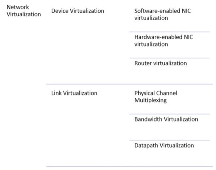
Network virtualization is a broad term that encompasses many different techniques. For e.g. traditional VPNs and VLANs are types of datapath virtualization, where the a physical link is extended virtually. Cloud data centers rely on a combination of all of these virtualization techniques to build a scalable, flexible and agile network. Virtual machines have virtualized Network Interface Cards, which bridge a unique virtual MAC address to the physical NIC. Router virtualization enables the creation of multiple tenant virtual networks, based on “map-and-encap”, where edge routers map the packet to the destination, then encapsulate packets within a network tunnel which are only decoded at the target node.
Bandwidth and physical channel virtualization are achieved by sharing slots within the network using traditional techniques like TDM/FDM and circuit switching. Datapath virtualization allows packets to travel along a programmable path, allowing flexible flows and traffic management. In the coming pages, we will also explore SDNs, which are an alternative to simple network virtualization.
In conclusion, cloud data centers rely on a group of techniques to decouple network services from the hardware network, making it easy to programmatically configure and deploy them.
References
- Liu, Yang and Muppala, Jogesh K and Veeraraghavan, Malathi and Lin, Dong and Hamdi, Mounir (2013). "Data Center Networks: Topologies, Architectures and Fault-Tolerance Characteristics." Springer Science and Business Media.
- Liu, Yang and Muppala, Jogesh K and Veeraraghavan, Malathi and Lin, Dong and Hamdi, Mounir (2014). "Problem statement: Overlays for network virtualization." RFC 7364.
- Wen, Heming and Tiwary, Prabhat Kumar and Le-Ngoc, Tho (2013). "Wireless virtualization." Springer.
Software Defined Data Centers and Networking
Network Virtualization
An application stack generally includes firewalls, load balancers, web servers, app servers, databases etc. Traditionally, these resources used to run on separate network segments as they needed to communicate with each other using a backplane network before responding back to the external user. In traditional data centers, the network was segmented using Layer 2 Virtual LANs (VLANs), which are a mechanism to restrict the broadcast domain of each LAN segment and partition the network.
Unfortunately, provisioning a VLAN to create a network segment is a highly manual task, which involves configuring a hypervisor vSwitch as well as the physical ports for all the switches in the network segment. Due to this manual configuration, VLAN scalability is poor (Most commercial network switches offer only a maximum of 4K VLANs). Server Virtualization led to an explosion in the number of virtual machines, which in turn increased the complexity of network infrastructure and services. Manual provisioning becomes almost impossible due to the scale and complexity which arises as a result of VM features like dynamic provisioning, placement and migration.
The complexity of these networks led to increased complexity of switching intelligence, which made networking hardware more expensive. It also led to vendor lock-in as most routing infrastructure has poor interoperability. Traditional networks lacked well-defined open interface standards. Finally, data centers were constrained by the properties of traditional network protocols, which did not adapt well to the dynamic relocation of resources, or the colocation of isolated servers.
Network Virtualization technology, and Software-Defined Networking provide a solution to this problem of many VMs, which can be placed dynamically and migrated in real-time within the data center. A virtualized network includes features like dynamic creation, deletion, migration, configuration, snapshotting, and roll-back of state.
Software Defined Networking
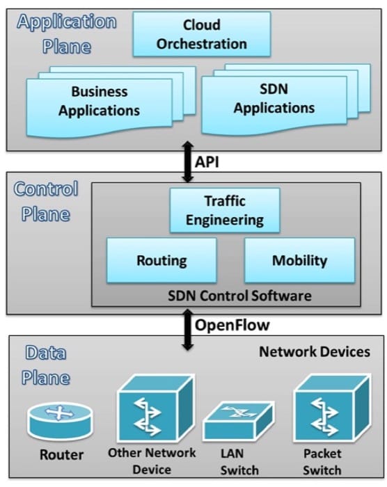
Software-Defined Networking is an approach to computer networking that decouples the data plane (that forwards packet in the hardware layer) from the control plane (which decides the packet forwarding rules). SDNs use a centralized controller, which programs the data plane using well-defined APIs to modify the network flow. See Figure 3.33 to understand the various pieces of the stack.
Video 3.14: Software Defined Networking
SDN Architecture
SDNs are remarkably flexible; they can operate with different types of switches and at different protocol layers. SDN controllers and switches can be implemented for Ethernet switches (Layer 2), Internet routers (Layer 3), transport (Layer 4) switching, and even at the application layer (Layer 7). SDN relies on the common functions found on networking devices, which essentially involve forwarding packets based on some form of flow definition.
From the point of view of an individual switch, a flow is a sequence of packets that matches a specific entry in a flow table. A Flow Table matches incoming packets to a particular flow and specifies the functions that are to be performed on the packets. A combination of Flow Table entries on multiple switches binds a flow to a path.
In an SDN architecture, a virtual and/or physical switch performs the following functions:
- The switch encapsulates and forwards the first packet of a flow to an SDN controller, enabling the controller to decide whether the flow should be added to the switch flow table.
- The switch forwards incoming packets out the appropriate port based on the flow table. The flow table may include priority information dictated by the controller.
- The switch can drop packets on a particular flow, temporarily or permanently, as dictated by the controller, for security purposes, curbing Denial-of-Service (DoS) attacks or traffic management requirements (congestion control).
The SDN controller manages the forwarding state of the switches using APIs that allow the controller to address a wide variety of operator requirements without changing any of the lower-level aspects of the network, including topology.
With the decoupling of the control and data planes, SDN enables applications to deal with a single abstracted network device without concern for the details of how the device operates. Network applications see a single API to the controller. Thus it is possible to quickly create and deploy new applications to orchestrate network traffic flow to meet specific enterprise requirements for performance or security.
The centralized SDN controller can be used to effectively provision, manage and tear down virtual networks over a physical IP fabric. The SDN controller provides a standardized API to a cloud orchestrating application to program the network elements in a data center to provide on demand virtual networks. In case a VM is migrated, the SDN controller will take care of modifying the flow tables in the network elements to re-establish the virtual network. This kind of flexibility cannot be provided if the configuration is done manually.
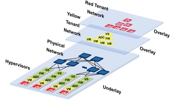
Using these techniques, SDNs create a logical overlay network that isolates the network components between different tenants, while simultaneously allowing VMs from the same tenant to exist on the same Layer 2 broadcast domain. This is allowed even if both devices physically reside in different data centers. By abstracting away the physical network, Cloud Providers can then allocate both private and public (Internet-facing) IP addresses to VMs, and even allow them to be dynamically re-located, without requiring any manual reconfiguration.
Isolation using SDNs
Having a central controller allows the control plane to have a global view. This reduces the need for complex protocols like Spanning Trees to compute paths. Instead a simple shortest-path algorithm (for e.g. Dijkstra) can be used to compute the topology. This removes complexity from the central plane, allows fast reconfiguration of network architectures, add and update security rules, all using a simple API.
Isolation between tenants is a critical SDN application on the cloud. By specifying separate network flows depending upon the tenant, multiple virtual networks can be overlaid on a single physical network. These virtual networks can even have overlapping IP address space. Consider the case with two cloud tenants-- Yellow and Red, colocated on the same rack in the datacenter (Figure 3.34). They can share the same underlying infrastructure, while being isolated using a higher-level abstraction.
One way to achieve isolation between the Red and Yellow tenant network is by using network tunneling. Typically, the following steps takes place for tunneling traffic,
- The application running on the VM considers it attached to a LAN segment and sends out an ethernet frame on the virtual network interface (VNI)
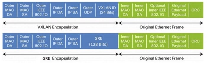
- The vswitch (virtual switch in the hypervisor) receives the packet from the VM and encapsulates it. The encapsulation method (Figure 3.35) may be any of the following,
- VXLAN (Virtual Extensible LAN)
- NVGRE (Network Virtualization using Generic Routing Encapsulation)
- The kernel ip-stack adds the destination mac and ip address of the target hypervisor and sends it out on the physical ip fabric.
- At the destination, the kernel ip-stack strips the outer mac and ip address and reads the encapsulation headers to determine the destination vm and delivers the packet to the VNI of the destination VM.
The overall flow of a packet from the source application to the destination application is illustrated in Figure 3.36:
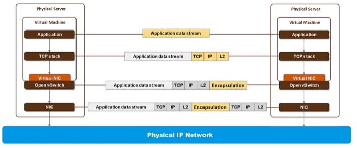
Software defined networking comes into the picture in steps 2 and 3 of the above tunneling process. The software running on the hypervisor vswitch, inspects the packets and requests the centralized SDN controller to add a flow specification for the flow. The flow specification is used to match the {VM, Source Address, Destination Address} tuple to a flow action that adds the Encapsulation Header and the outer MAC and IP header as shown in Figure 3.35. The SDN controller knows what outer header to add because it has a global view of all the resources and the software on the controller route the flows accordingly.
Storage within Data Centers
Typical Data Center Storage Systems
In previous units, we discussed the various types of on-line storage devices that are in use - primarily magnetic and solid-state drives. We also looked at how these devices can be deployed in a number of ways in a data center. They are reproduced here for your convenience:
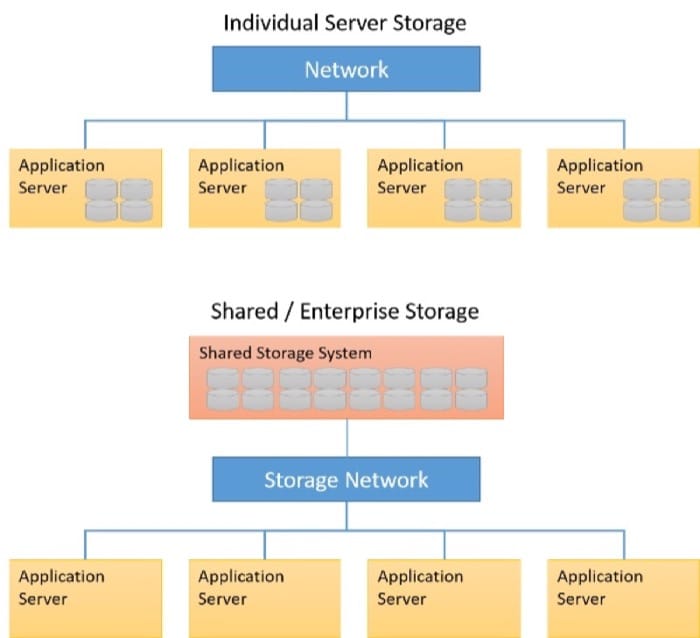
- Individual Server Storage: This is a typical storage architecture that you are familiar with, where individual disks are present on each server. This type of configuration is usually the cheapest option as it does not require any specialized hardware or networking devices, but also requires the most amount of management; Disk failures may cause data loss and/or loss of availability unless the server applications are explicitly replicating data and are configured for fault tolerance. Due to the lower cost of hardware, this type of storage is typical in large-scale data analytics clusters that run frameworks such as Hadoop or Spark, where fault tolerance and reliability are dealt with in the software and cluster architecture.
- Shared/ Enterprise Storage: This refers to storage architecture that is decoupled from individual servers, typically through the use of a dedicated storage servers, arrays or appliances. These systems provide shared storage (either as block devices, file systems or object storage systems) to multiple servers. These systems are connected to the servers using either a regular Ethernet network, or using dedicated storage network fabrics (such as Fiber Channel or iSCSI over Ethernet). The benefit of this approach is the loose coupling of servers and storage, allowing for the components to be individually configured and upgraded as needed. This is a popular approach used with many applications, including database-driven applications, small to medium web services and IaaS cloud providers. Specifically for IaaS services, the ability to spin up a virtual machine with attached virtual disk images is made much simpler by the use of shared storage systems.
Typically, enterprise grade storage systems are specified, configured and deployed based on the needs of an application. For example, a content delivery server may require a storage system that is vastly different from one that meets the requirements of a transactional database for a bank, for example. A content delivery server may require higher bandwidth to transfer large amounts of data to clients (such as photos or video), while a transactional database for a bank requires fast, low-latency transactions (which are small amounts of data), with strong backup and persistence guarantees. Traditional infrastructure deployments would include storage specifications that are optimized to the needs of the application deployed on the infrastructure.
With the advent of cloud computing and multi-tenancy in the data center, different users may have very different storage needs. However, they are restricted to the service offerings of the cloud provider, which may not have enough granularity to express the exact requirements of the user’s applications. Users may specify service-level objectives (SLOs) with regards to storage such as a certain capacity and latency or bandwidth requirement of their application. In addition, these requirements can change dynamically as the application is running; users would like the flexibility to vary their storage requirements based on their demand. For example, in Amazon Web Service's Elastic Block Storage service, users can specify a specific amount of provisioned IO Operations per Second (IOPS) that they expect to get from the virtual disk, users can, for a price, demand higher throughput and lower latency from storage services. However, designing systems that can dynamically serve these types of resource requests is challenging.
Software Defined Storage
As you have already seen, different types of storage systems can be deployed based on the needs of an application. The most basic form of storage is direct-attached storage, wherein storage devices such as Magnetic disks or SSDs are directly attached to a server internally (through an internal bus connection, typically SATA or SAS). On the other hand, massive, enterprise grade storage systems can be used in the form of a Storage Area Network (SAN), which use a network (using different technologies) to connect servers to a pool of disks.
Recall that in clouds, physical compute resources are shared among multiple tenants through virtualized servers. This approach could also apply to storage resources as well. Storage resources can be shared among multiple tenants, allowing for the lowering of cost and improving overall utilization of these resources. However, a form of isolation should be provided along with fault tolerance and other technologies to meet a specific application's SLOs. This enables clients to have predictable behavior of their applications, while sharing storage resources with other tenants. Providing end-to-end SLOs would translate into requirements on bandwidth, Input/Output Operations Per Second (IOPS), priority or control over the entire IO path (Figure 3.38).
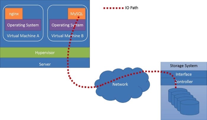
Software Defined Storage (SDS) allows clients to specify fine-grained capacity, latency and/or bandwidth requirements, in the form of SLOs, which are mapped to abstract storage services for the client. The cloud provider can assemble and provide a scalable storage service using various storage technologies in the back-end. Client SLOs can be met by managing the storage stack at the provider's side.
Video 3.15: Software Defined Storage
To better understand how this can be achieved, let's look at one of the emerging technologies that enable SDS, IOFlow [1] .
An Example of SDS: IOFlow
In data centers, the operation of an application requesting file operations and the storage system fulfilling the operation is complex involving several stages such as the host OS, the hypervisor, the network fabric, the storage server and finally a disk operation. The request also appears differently at each layer. For example, a file IO request like a read, write, or create in a VM results in a block IO request in the hypervisor. This, in turn, results in Ethernet packets across the network, and finally another file IO request and block device request at the storage server.
The number of layers in the system means that enforcing an end-to-end flow policy (these policies are typically derived from an SLO) is hard. It requires layers along the IO path to treat requests differently based on their content and/or client SLOs. Further, policies may need to be enforced at one or more or all layers along the path. For example, prioritizing IOs from a specific VM to storage requires configuring the prioritization on all layers along the path.
IOFlow is a software defined storage architecture, designed by Microsoft, to maintain end-to-end SLOs, bandwidth SLOs and also improve performance. The clients are VMs running on compute servers through a hypervisor. These VMs need access to the storage server which is regulated by IO-Flow. Data flow is achieved by the use of queues at each stage in the IO path. These queues are regulated by a centralized controller. The centralized controller in the IOFlow architecture assigns data rate metrics and the route at each stage in the overall architecture.
An example of a typical VM to storage server IO path is presented in Figure 3.39 below. A compute server, which consists of a number VMs running simultaneously interacts with a storage server. Thus, the application interaction with a filesystem within a VM becomes block device requests at the virtual hard disk (VHD). In this specific example, the virtual hard disk is actually a remote storage server serving files using Microsoft's SMB protocol. Therefore, IO requests further get translated into a network packet at the hypervisor's network driver and sent across to the remote storage server through the network. In the storage server, the network packet is unwrapped at each layer, transforming into an SMB request, which in turn translates to a file system request at the storage server. At each layer in this IO path, IOFlow adds a queuing abstraction, which is then exposed to the IOFlow controller. The controller can translate these policies into lower level queuing rules at each stage.
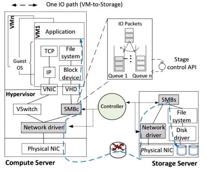
The IOFlow controller regulates IO traffic in the following manner:
- The IOFlow controller obtains a graph of the entire network under it, including where the compatible stages are located.
- Policies (explained below) supported by the controller are chosen by the client.
- Based on the client's policy, queues are formed and configured at intermediate stages.
- When IO traffic passes through these intermediate stages, the IO header is recognized and the respective policy is implemented.
IOFlow implements flow identifiers, which are basically IO headers attached to individual IO requests, these low level headers are attached to the IO as the high level headers and cannot be recognized by the intermediate stages. Once the intermediate stages identify a header they use it as routing information, to route the IO to the next hop.
As an example of how SDS can use policies to regulate IO traffic, IOFlow currently presents the following five flow policies:
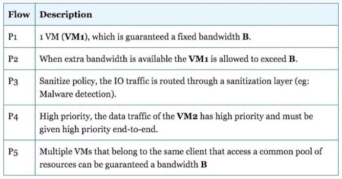
For P1, every VM is promised a minimum bandwidth to access one or more storage servers. However, in P2,if there is extra bandwidth available, as a result of one of the peer VMs having gone idle, the bandwidth available to VM1 can change dynamically. P3 requires traffic to be routed to a layer for sanitization. As an example, a new untrusted VM can have its traffic routed to a malware detection system. P4 can ensure low latency operations by assigning high priority to VM2 storage traffic. P5 allows a bandwidth guarantee for a set of VMs that need to access specific storage servers. The policies P1 through P4 are specified for point-to-point flows, while P5 policies are specified for multiple flows.
SDS is a fast evolving approach to providing storage as a service which meets a client's SLOs through shared storage systems. As mentioned above, sharing without end-to-end SLO guarantees will not be readily adopted. IOFlow is an early example of an SDS technology. We expect the innovation in the SDS space to continue at a rapid pace bringing with it new solutions that will attempt to meet new cloud application requirements.
References
- Thereska et al. (2013). "IOFlow: A Software-Defined Storage Architecture." SOSP'13: The 24th ACM Symposium on Operating Systems Principles.
Summary
- A Software-defined Data Center (SDCC) automates and makes infrastructure easy to manage by virtualizing all components within a cluster, including servers, networking fabric and storage systems.
- Software-defined Networking (SDN) and Software-defined Storage (SDS) are emerging technologies that are showing promise in improving the flexibility of data center design, while also improving utilization and isolation.
- Data center network designers have to carefully select the topology, addressing scheme, traffic shaping policies, and fault-tolerance mechanisms.
- In multi-tenant networks, there is a strong need for virtualization, as overlay networks are constructed to allow tenants to flexibly share network resources.
- Virtual networks can be provisioned, migrated, reconfigured and snapshotted just like virtual machines.
- Software-defined Networking (SDN) is another alternative to basic virtualization, whereby the data plane is decoupled from the control plane of the network.
- SDN may rely on central controllers to make routing decisions, and help in tunneling packets by adding appropriate header information based on a global view.
- Cloud data centers rely on shared storage mechanisms to quickly create volumes for many virtual machines. The sharing is generally done over a high-speed network fabric.
- SDS is a recent approach to provide storage as a service that meets a client SLOs. An example of an SDS system is IOFlow, which allows the application of policies such as data rate metrics or malware detection on IO traffic.