云计算 阅读材料 4 Data Center Components
本页目录
In this module, we will discuss the various components (equipment and facilities) of a data center. We will start with a discussion on IT equipment, and will clarify many server-specific terminologies that you may have encountered. Most hardware vendors provide servers that are configurable in terms of compute, storage and networking. We will present in detail these server components. While these topics can be information-dense, the choices made while configuring servers have a major impact on the cost and performance of applications that are run on them. Therefore, an exposure to the spectrum of servers and related technologies will be useful, especially if you pursue a career that utilizes or manages cloud infrastructure.
Also, in this module, we will discuss data center facilities. Specifically, we will present some of the recent advances in power and cooling techniques which provide additional efficiency to today’s data centers. We also cover a few additional facilities-specific aspects regarding fire and safety in data centers.
IT Equipment
In this section, we define IT equipment as anything that is mounted in a rack (called rack-mounted equipment). This equipment typically includes servers, dedicated storage arrays, network switches and routers, power distribution, and remote management devices. We are specifically referring to a four-post rack inside a cabinet enclosure. Additional types of racks are described on the next page of this module ("Facilities").
Servers
A rack-mounted server is similar to a tower PC, except turned horizontally and made to fit into a thinner, deeper chassis (Figure 2.7). The heights are measured in multiples of rack units, where 1U = 1.75 inches (4.45 cm). A 1U server can be CPU and RAM dense but leaves little room for I/O expansion cards (usually two). A server that is 2U or 3U can have six to eight I/O card slots. Smaller chassis must also have smaller fans and therefore make considerable noise compared to your average desktop computer (this is acceptable because most server rooms are not occupied by humans). Systems that are 4U, 5U, or larger chassis usually have a specialized function: one example is an 80-core Intel server, which has CPU sockets and RAM on vertically mounted daughter cards; another is a quad-GPU accelerator server; a third is a server chassis with a 24, 36, or 48 internal hard drives.
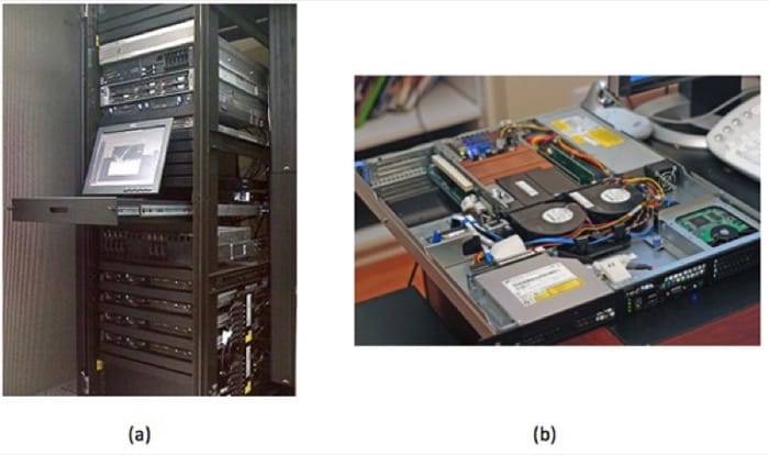
Rack-mounted servers have their own fans, power supply units (PSUs), network, and I/O, but blade servers share all of these across many nodes within the same blade enclosure (called blade chassis). There is no common blade standard, so each vendor's blades work only with its enclosures. Blades are thin, vertical metal enclosures and slide into the front of a blade chassis and attach to a common backplane. Each blade has its own motherboard, CPU, RAM, and disk. The shared PSUs are typically more efficient than dedicated rack-mounted versions because they can power up or down incrementally, adjusting PSU capacity to load demand. For example, instead of 10 servers with 2 * 750W redundant PSU, a blade enclosure can power the equivalent of 10 servers with 4 * 2500W PSU, with one being redundant. Blades are denser than their horizontally mounted counterparts, allow for easier maintenance, and require fewer cables. The disadvantage is higher upfront cost if you only need a few servers, plus you are locked-in to a specific vendor.
Last, there are a few servers that look similar to a standard rack-mounted server, except they have two motherboards horizontally per 1U, each mounted on its own tray. They also share a PSU but, unlike blades, have their own fans and I/O. There are variations on this theme, such as four nodes per 2U or two nodes with multiple GPUs.
Did you know? A 1U rack-mounted server is sometimes referred to as a "pizza box."
The following video (Video 2.2) describes various server form factors:
Video 2.2: Server Form Factors.
An important feature found in most rack-mounted servers is hot-swap capability. Components such as PSU, fans, and hard drives can be removed and replaced while the server stays running. This feature increases uptime/reliability on small- and medium-scale deployments. Large-scale application deployments require more sophisticated resiliency to be built into software layers, which is discussed in the next unit. These large-scale systems do not use hot-swap or redundant components for individual servers but instead consider the entire server to be failed (and replaced) as a unit.
The electrical components (e.g., capacitors, voltage regulators) of a server are typically more expensive and longer lasting than those parts used on desktop systems because the servers are designed to run 24/7 for many years on end. A workstation is similar to a server class computer, with similar CPU, high RAM capacity, and added reliability. The difference is that a workstation sits at the user's desk, so it requires quieter fans. To add to the confusion, there are also rack-mount workstations, which are just like a server, but have remote viewing capability, so the end user sits at a thin client.
Newer servers are now being designed to run reliably at higher ambient room temperatures (up to 95°F, or 35°C), which decreases cooling requirements and therefore lowers operational expense.
On the Motherboard/Mainboard
CPU and memory: A typical server motherboard has more CPU sockets than a desktop system, and each of those sockets can control more DIMMs (dual inline memory modules). Another primary difference of server-class CPUs versus desktop class (Intel Xeon versus i3/i5/i7; AMD Opteron versus FX/A/Phenom) is more onboard cache, support for registered DIMMs, and support for error-correcting code (ECC) RAM.
Server-class CPUs also have dedicated circuitry that allows them to communicate with each other through dedicated channels in the motherboard. For Intel, this is known as QuickPath Interconnect (QPI), and for AMD, it is known as HyperTransport (HT). These follow a nonuniform memory access (NUMA) model, in which processes running on other CPUs (sockets) can access large amounts of RAM by going through QPI or HT to the RAM attached to another CPU. Combining high-density, registered DIMMs (16GB or 32GB), more DIMM slots per server (9 or 16), and multiple sockets with onboard interconnect, a single server can have 512GB or even 1TB of RAM available to a single process (although you get higher performance when you have multiple processes with multiple threads each, but that is a topic for another course).
Onboard management: Although many desktop motherboards now have onboard gigabit Ethernet (GigE) networking, this trend started with servers, and on modern servers, you will find two to four GigE ports. Other onboard devices that a server includes are a serial port for console redirection and an embedded management controller, which allows remote management even if the system is powered off (but still plugged in) or if the OS is not responding (i.e., kernel panic). Many server motherboards have onboard hard drive controllers, but these are also common in the form of an expansion card, which is discussed below.
Expansion cards
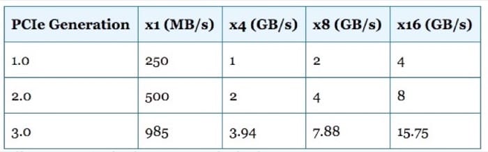
PCI Express: Often, a server requires additional I/O devices, depending on the applications intended to run on it. PCs and mainframes have always had some notion of expandability, and expansion buses have evolved from ISA to PCI to PCI-X to what is the current standard—PCI Express (PCIe). The biggest difference between PCI and PCIe is that PCIe is based on point-to-point, high-speed serial links, rather than an actual bus, which has multiple devices attached. Each of these high-speed links constitutes a lane, and multiple lanes work in parallel. So a PCIe device that is x8 has eight of these high speed lanes. Each generation of PCIe, from 1.0 to 3.0, effectively doubles the bandwidth of the previous generation.
RAID: RAID (redundant array of inexpensive disks) adapters allow multiple hard drives to act as a single logical unit, with increased performance and redundancy or a mixture of both.
| RAID Level | Name | Advantages | Disadvantage |
|---|---|---|---|
| 0 | Called block-level striping | Improved performance | No fault tolerance, and a single drive failure destroys the entire array |
| 1 | Called mirroring because data is replicated entirely. | Can withstand drive failure. It has faster reads (sometimes), and this level maintains performance on failure. | One-half the capacity versus two independent drives. This level has slower writes. |
| 10 | Called RAID 1+0 or ten (mirroring+striping). It combines the speed of RAID 0 and redundancy of RAID 1. | Provides fault tolerance. It has improved performance. This level maintains performance on failure | One-half the capacity versus two independent RAID 0 arrays. |
| 5 | Block-level striping with distributed parity. | This level can withstands single drive failure, and it has more capacity versus RAID 1, 10, and 6. | Slower writes than RAID 0, 1, and 10, degraded performance on failure, and slow rebuild process. |
| 6 | Block-level striping with double-distributed parity. | Withstands two drive failures and has more capacity versus RAID 1 and 10 (with more than four drives). | Slower writes than RAID 5, degraded performance on failure, and slow rebuild process. |
Table 2.2: Different RAID levels with major advantages and disadvantages.
RAID controllers come with different number of ports (connected drives), support different interfaces (SATA, SAS), vary in amount of built-in cache (e.g., 512MB, 1GB), and have varying performance levels (MB/s throughput, I/O per second). Each of those factors can change the price of the adapter (from a few hundred to over $1000).
A host bus adapter (HBA) is similar to a RAID controller, except that it connects to external storage (discussed in the next section) and does not typically include any RAID features on the card itself. The card will encapsulate all communication, so the remote disk device will look like a local disk to the OS and is bootable.
Networking support: Ethernet network adapters can include single or multiport cards, with speeds ranging from 100Mbps (obsolete) to 1Gbps (common, inexpensive), then came 10Gbps (becoming more prevalent but still expensive), and now 40Gbps (available but not common yet).
A host channel adapter (HCA) refers to a high-speed, low-latency interconnect adapter, such as Infiniband. These are typically used on high-performance computing (HPC) clusters.
Solid-state storage cards are now available, such as those from Fusion-IO. They provide much faster performance than RAID controllers, especially on random I/O. They have a very high cost per gigabyte compared to hard disk drives (HDDs) or even solid-state drives (SSDs) (see the following "Storage" section).
Accelerators: Video cards, started in desktop computers, use GPUs for fast 3D rendering. These GPUs can also be used for scientific computation, so they made their way into HPC server markets, and now nVidia Tesla series accelerators can be found in more than 50 of the top 500 supercomputers list. Recently, Intel released an accelerator product, the Xeon Phi, which is based on Many Integrated Cores (MIC) architecture and is similar in performance to Tesla product (>1 teraFLOPs). These cost approximately $3000 but can increase performance 2.5x to 10x (often) to 100x (atypical) for math-intensive applications. Note, however, that these will not fit into your average server case due to the large size of the card and additional PSU requirements.
Server Configuration
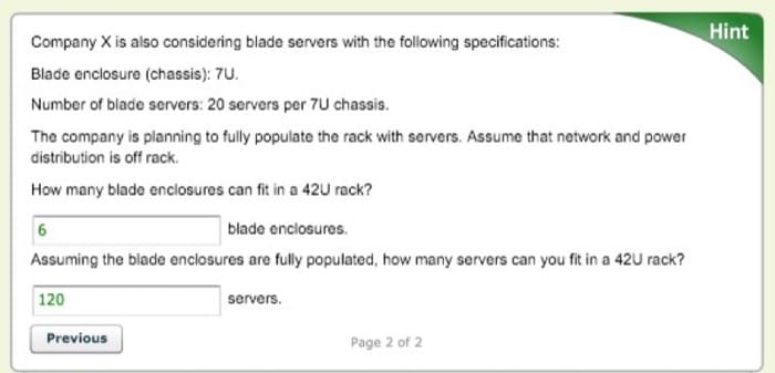
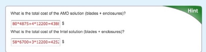
Company X wants to expand its private cloud for hosting a new Web application composed of many Linux virtual machines running in a VMware ESXi 5 environment. They do not want to use more than one rack of equipment, so they like the density that blade servers provide. They have benchmarked their application and found that a blade server with 2 x Intel Xeon E5-2660 performs 40% faster (i.e., 1.4x) than a blade server that has 2 x AMD Opteron 6276 CPUs. They use a fast QDR Infiniband network and fast enterprise-class SSD drives in each blade server, so the only bottleneck for the applications is the CPU.
Each blade enclosure/chassis is 7U tall and can house 20 blade servers (each blade is a two-socket blade). The enclosure itself costs $12,200 and includes power supplies, fans, gigabit Ethernet, and Infiniband network switch modules. These particular blades must be bought in pairs because of the way they stack in the enclosure.
The price of the Opteron 6276 processor is $850 (per socket). The price of the Xeon E5-2660 processor is $1370 (per socket).
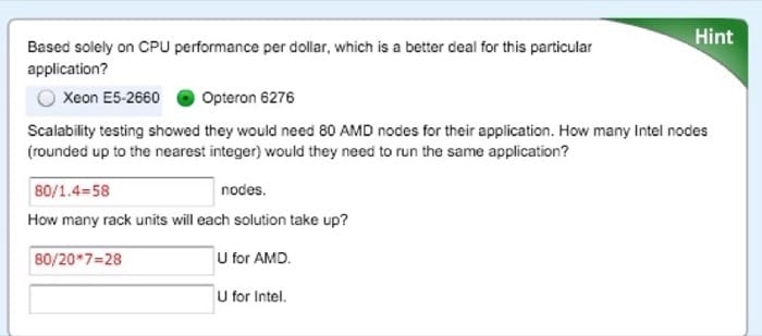
Configured to Company X's requirements, the AMD blade servers cost 6700 each. The company intends to configure the enclosures with the exact number of blade servers as determined in the scalability testing mentioned above.
Storage
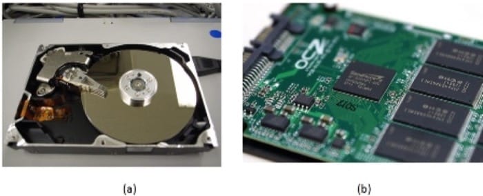
When most people hear the word storage, it is likely that they will envision an HDD (Figure 2.8(a)). Inside an HDD, the rotating platters and moving read/write head have been similar for decades. What has evolved are higher areal density, new recording techniques, faster interfaces, and overall lower power. The two most common form factors of HDDs are 3.5 inches and 2.5 inches. Rotational speeds can vary, but common RPM values are 5400, 5900, 7200, 10,000, and 15,000. The higher the RPM, the lower the latency between random seeks.
Did you know? The maximum physical capacity of a hard drive is governed by what is called the superparamagnetic limit.
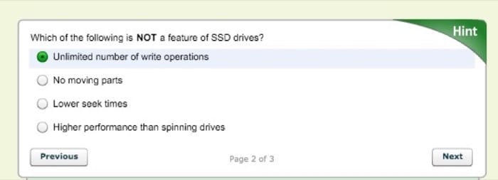
SSDs (Figure 2.8(b)) are becoming more affordable but still have a much higher cost per gigabyte than their mechanical counterparts. SSDs are completely electronic; there are no moving parts, which gives lower seek times, higher performance, and higher reliability. SSDs do have a limited number of writes, but one would have to continuously write to the drive 24 hours a day for several years to reach that limit. The terms SLC, MLC, and TLC refer to how many voltage levels there are in each cell: S is for single (1), M is for multi (2), and T is for triple (3). The fewer the levels, the more reliable it is (SLC > MLC > TLC). The more levels, the higher the density (TLC > MLC > SLC). SLC is generally reserved for high-throughput transactional servers. MLC is the most common replacement for desktop and laptop drives, plus servers that need higher I/O performance than a fast (10k or 15k rpm) HDD can provide. TLC is emerging as a lower cost alternative to MLC, but somewhat compromises performance and reliability to achieve a lower price.
The hard drives that are found in data centers are nearly identical to those found in desktop PCs. The primary difference between an enterprise and a regular SATA drive is added antivibration protection, which claims to increase the lifespan of drives that are rack mounted with many other drives in the same chassis. They also come with longer warranties—5 years instead of 3.
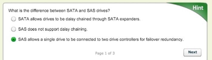
SATA (serial ATA) and SAS (serial attached SCSI) are the two predominant interfaces for all modern HDDs and most SSDs. For servers, SAS provides the ability for a single drive to "talk" to two drive controllers (in case one controller fails). SAS also requires lower CPU usage and provides the ability to daisy chain a large number of drives via an SAS expander. Most RAID controllers that support SAS also support SATA, but the inverse is not true.
Direct attached storage (DAS) refers to a rack mount chassis that holds additional drives, along with PSUs and fans, but minimal control logic. All of the work is done by the controller (on the server) that these units attach to. A typical connection is made through external SAS cable (high-speed serial, multilane, copper).
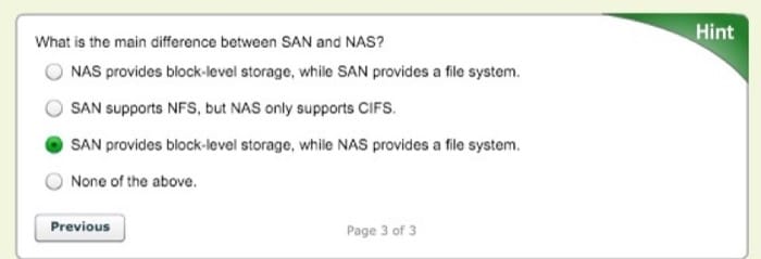
A storage area network (SAN) is a collection of hard drives in a chassis that can be connected to many servers. A system admisinstrator will carve the array into LUNs (storage logical unit numbers), where each LUN can be used for a different purpose. Many servers connect to the same SAN simultaneously, but only one server accesses a given LUN at a time (unless a coordinated sharing software is installed, such as VMware). Servers connect to the SAN through a network, typically Fibre-Channel or iSCSI over Ethernet (1Gb or 10Gb). Each LUN gets a unique World Wide Name (WWN), which can be used for zoning and masking, providing security so that servers can only read the LUNs that belong to them. Access can also be restricted by IP and subnet.
Most commercial SAN products span multiple rack units or even multiple racks, and have multiple redundant controllers and network paths to increase uptime. SANs have embedded RAID controllers, so disk failures are transparent to the attached servers. SAN products vary greatly and, depending on features, performance, and capacity, can range from $5000 to several million US dollars.
Network attached storage (NAS) is a device or server that shares a file system to multiple users over the network. Any Linux server can become a NAS, and many consumer dedicated NAS devices run Linux underneath. The two most common protocols used by a NAS are called CIFS (Common Internet File System, also called SMB [Server Message Block]) and NFS (Network File System). CIFS comes from Microsoft Windows' heritage and is a per-user connection in which NFS is primarily used on UNIX/Linux and is a per-host connection.
Last, there are also many Distributed Parallel File Systems, which are typically used in compute clusters and implement a many-to-many scheme. These provide a much higher combined throughput than any single SAN or NAS and can scale in both performance and capacity.
The choice on which type of storage to use is largely dependent on the application, and most organizations will use a combination of the above. For example, a large storage array uses a parallel distributed file system on its internal back-end network but presents both SAN-style LUNs and provides NAS capability for other clients. A Windows file server will look like a NAS to a client mapping a network drive, but it is likely that the storage device in which files actually reside are in a SAN, which is outside of the Windows server itself. When you learn about resource sharing in the next unit, some of those features (live migration, fault tolerance) require a SAN storage device.
Networking
In addition to servers, a data center houses all of the network equipment that is used to connect those servers to each other and to the outside world.
One popular design is the multitier topology (Figure 2.9), in which servers connect directly to switches, and those switches link to aggregation switches, which, in turn, connect to the rest of the organization's network (i.e., core switches) and eventually to the upstream ISP.
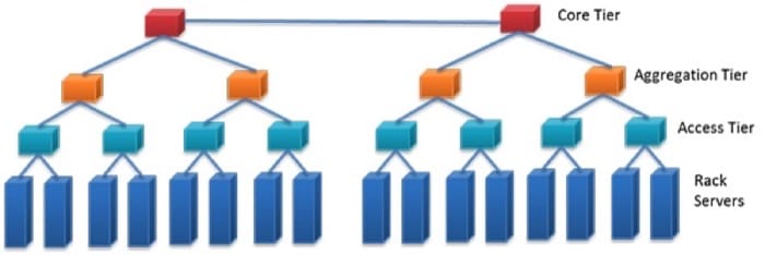
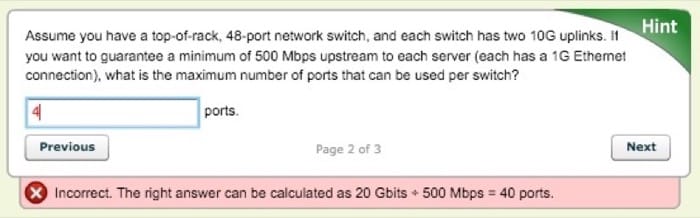
A fatter (higher bandwidth) connection typically links the bottom-tier and aggregation switches. For example, with 48x1Gb ports connecting the rack servers and the access tier, the access to the aggregation tier might have 2 * 10Gb uplinks.
Top of rack (TOR) refers to a configuration in which the lowest tier of network switches are found in each rack. This design can decrease cabling cost and complexity because the wires are shorter and can be copper even at 10Gb speeds. This is especially useful if most of the network traffic is to other servers in the same rack. Apache Hadoop, for example, can take advantage of this topology for choosing which nodes to store data (on rack and off rack) and which nodes from which to retrieve data (on rack). One disadvantage includes limited scalability. Ethernet switches are blocking, which means that if all the ports are busy at the same time, the backplane cannot handle all the traffic, so some requests are postponed. Also, the uplinks that are available are typically less than the full possible bandwidth of the Ethernet switch (e.g., you cannot have a 48Gbps uplink on a 48x1Gb switch). In most real-world scenarios, however, those uplinks are never saturated because not every server is using the full capacity simultaneously. Another disadvantage is port utilization. Switches come with a specific number of ports, typically 24 or 48, so if you have a number of servers in between that, you will have some ports in each rack that are never used.
End of row (EOR) refers to a configuration in which you have a row of adjacent racks, or a row of back-to-back racks,sometimes called a bay, and there is one additional rack dedicated for network switches, and all of the hosts in that row (or bay) are wired to that dedicated rack. Wiring is either done above the racks in a wiring tray or below the racks, underneath a raised floor (more on that in the next section). The switches in this dedicated rack can be a larger (10U+) modular chassis, in which each module communicates to other modules through a fast backplane. The advantage is that all servers in the same row (or bay) can communicate with each other at the same speed (and lower latency), so there are fewer bottlenecks. The disadvantage is higher upfront cost and more complex cabling (harder to debug if there is a problem). Gigabit links can still be copper at this distance, but anything 10Gbps or above should be fiber.
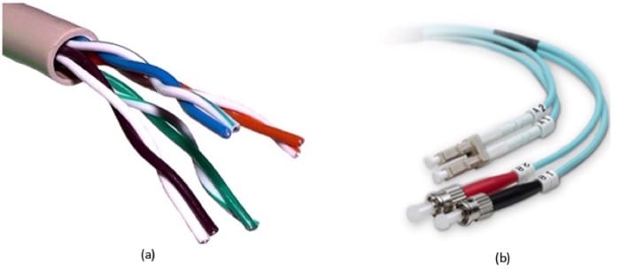
Ethernet is by far the most popular type of network in data centers (and elsewhere in organizations). Although its rise in popularity started in the 1980s with 10Mbps, both that and 100Mbps products are obsolete because of the low price and ubiquity of 1Gbps products. The primary driver for Ethernet popularity is the low cost and ease of installation of twisted pair wiring. The most common type of Ethernet wiring is unshielded twisted pair (UTP) (Figure 2.10(a)), which has four pairs of thin (28awg) copper wires and comes in different categories: category 5 (Cat5) is good for 10/100Mbps, Cat5e and Cat6 are good for 1Gbps, and Cat7 can go up to 10Gbps. Each generation has slight design changes over the previous, which allow for greater bandwidth and/or longer runs. Alternatively, shielded twisted pair (STP) has an extra metal shielding on the outside for use in electrically noisy environments (such as a factory or near high power lines). The shielding reduces interference but is generally not needed for most in-rack installations.
Ethernet can also travel over fiber (sometimes fibre) optic cable (Figure 2.10(b)). Fiber is unidirectional, so in a cable, you will see two strands, one send and one receive. The electrical signals are converted to photons, which stay inside the fiber due to the differences in indexes of refraction between the core (thin center) and cladding (thicker outside layer). The cladding is covered by a layer of fireproofing material. Fiber cables are thinner and lighter than copper cables, but care has to be taken in routing to maintain a minimum bend radius, otherwise some photons escape causing loss. Multimode fiber is most commonly used inside data centers because the cables and transceivers are much less expensive than single-mode fiber. Single-mode fiber is generally reserved for long-distance (>100m to 40km) connections. Higher speed Ethernet of 40Gbps is actually 4x10Gbps links that work in unison (similar to PCIe lanes); similarly, 100Gbps is 10x10Gbps (copper, fiber) or 4x25Gbps (fiber only).
Fibre Channel (FC) is a protocol designed to support SANs and remote block-level storage devices. Even though it typically runs over fiber, it can also run over copper. It can also be encapsulated in Ethernet in the form of Fibre Channel over Ethernet (FCoE) but is not routable like iSCSI. Fibre Channel HCA and switch generations are named by their speed (in Gbps)—##GFC, in which ## is 1, 2, 4, 8, 10, or 16. The most common now is 8GFC, which supports 8Gbps links (approximately 800MB/s in each direction).
iSCSI, or internet SCSI (pronounced "scuzzy"), is a protocol which packetizes SCSI (Small Computer Systems Interface, an old hard drive standard) commands to be transported over LANs or WANs. Many SANs support iSCSI, and it is popular because you can use your existing Ethernet network instead of deploying a dedicated FC network.
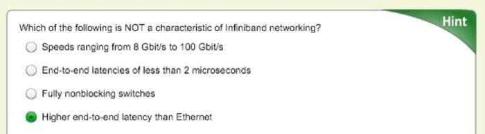
Infiniband (IB) has been popular in HPC clusters for almost a decade and is also gaining traction in other areas in the data center. The main advantage of Infiniband is much lower end-to-end latency compared to Ethernet (1.7 microseconds versus 12.5 microseconds for 10GigE versus 30 to 100 microseconds for GigE). It also scales better with the number of nodes in a cluster. The other key factor in IB performance is that the switches (Figure 2.11) are fully nonblocking, which means that the backplane supports running every single port at full speed, in both directions. Infiniband speeds are summarized by the chart below:

Infiniband and 40Gbit Ethernet are also being deployed as a converged network, or virtual fabric, which, along with virtualization of the OS, allows many virtual adapters (Ethernet, FC-HBAs) to run over fewer high-speed links. The connections can be configured dynamically through software and allow for fewer cables and easier maintenance and management.
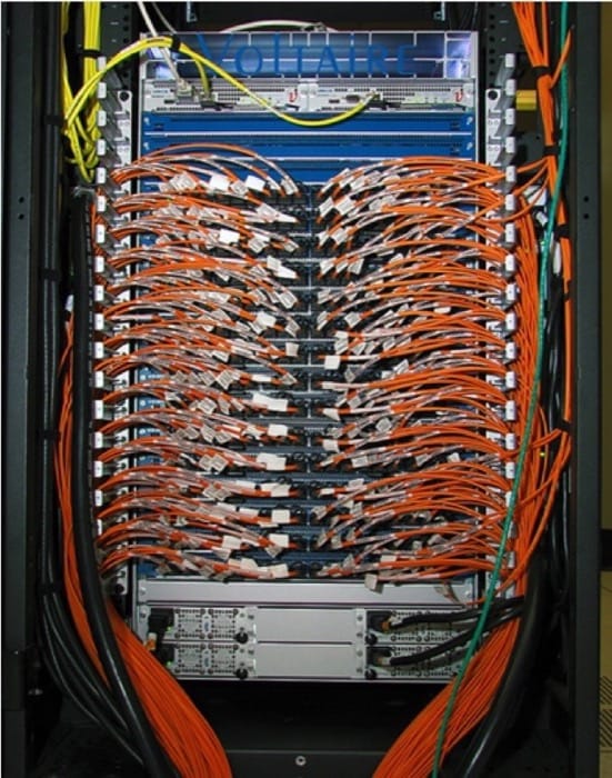
The choice of network technology and topology to deploy in a data center also depends on your applications but will typically include multiple tiers, with the connection between the tiers being high-speed fiber. Copper UTP cabling is prevalent within the rack and will continue to function well for low-speed management networks.

Infrastructure and Facilities
Data Center Facilities
A data center's functional units (servers, storage, networking) all rely on a facility's infrastructure, which includes physical space, power, cooling, and safety. In assembling each of the latter component systems, designers prioritize redundancy issues. Redundant power sources, for example, minimize the risk of service outages should the building lose main power. Redundant cooling avoids physical damage to IT equipment during an unplanned outage and enables planned outages for HVAC equipment maintenance.
Server Room
A server room can vary in size from a single rack in a closet to several hundred square feet to a warehouse the size of a football field. Some authors use the phrases server room and data center interchangeably. For the purpose of the course, we define a server room as the actual room that houses all of the racks full of IT equipment, and a data center as the server room plus all of the power and HVAC equipment that may be located outside of that room.
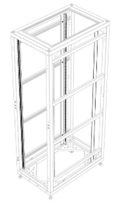
You were already introduced to the concept of a rack and a rack unit (U). Figure 2.12 shows a rack inside an open cabinet. Sometimes racks are also called cabinets. There are several variations of racks, but the most common are 19 inches wide (measured from the center of each hole on the same U). Some IBM equipment racks measure 24 inches post to post, inherited from older mainframes. Usually, network equipment is designed to mount only on two posts of the rack because wiring closets often have only two posts permanently mounted to the floor and/or wall. Servers, however, are designed to mount on four-post racks. The depth of the rear two posts is not standardized, and in most racks you can adjust the depth. Different rack-mount equipment has different depths, and each server or storage array will come with two mounting rails that connect to the front and rear posts on the left and right sides. There are two types of holes in vertical posts, square and round. Some mounting rails hook directly into square holes and have tool-less installation (fast). For round-hole racks, equipment is directly screwed in (these are more popular for telecom and A/V racks). If you need to mount round-hole style equipment or rails into a square-hole rack, you use cage nuts and bolts.
The most common height rack is 42U, and that is simply to fit through a normal doorway. The overall height, width, and depth of racks by different manufacturers are not exactly the same; the only guarantee is the post widths. Some racks have extended depth, which is useful for larger servers and/or routing cables and mounting zero-U (vertical mount outside of the 42U space) equipment. "Wide" racks have extra space to the left and right of the posts, which is useful for end-of-row networking racks because of the added space to run many cables. Racks also have casters that allow them to be rolled into place or moved if needed. However, these wheels are not meant to permanently support the full weight of a filled rack, which is why you have to screw down the four stabilization feet at each corner. Regions that are prone to earthquakes also have safety regulations that require racks to be bolted into concrete through metal plates on the front and rear of the rack.
Many server rooms have a raised floor, although it is not a strict requirement. This provides a plenum for cold air to be distributed throughout the room (tiles in front of racks have vent holes). Raised floors also provide space to run electrical or network cable or chilled water pipes for in-row cooling. Last, they provide more flexibility for future layout/configuration changes. Figure 2.13 shows what a raised floor looks like.
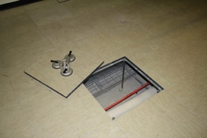
The floor consists of an array of metal support pedestals, which are mounted to the subfloor; metal stringers that are placed horizontally between pedestals; and strong floor tiles that rest atop the stringers at each corner at a pedestal. When a tile is removed, the holes are large enough for a human to fit through, and the tiles are strong enough to withstand the weight of a filled rack. Tiles do have a rollover rating, however, and for safety reasons, any tile that has been rolled over (moving a filled rack on top of it) more times than it is rated for should be replaced. Also for safety reasons, on a stringerless floor, no more than two or three consecutive tiles should ever be lifted from the floor simultaneously. If there is a problem with one of the pedestals, weight can shift laterally, cascading to a catastrophic floor failure.
Above the racks are cable trays that run horizontally between racks. There are options to hang these from the ceiling, or some racks have optional trays that mount on top. For electrical safety, these are required to be properly earth grounded, even if they are carrying only network cable. When there are a many wires to run between two racks, hook-and-loop (Velcro) fasteners are most often used to bundle the wires together.
Most data centers implement strict physical security procedures—for good reason. If someone with bad intentions had physical access to a server, they could, for example, gain administrative privileges, steal data, eavesdrop network connections, and install viruses/Trojans. Common practice includes keycard/pin access and/or biometric scanner, full time security guard, cameras, and break-in detectors. In shared data centers with multiple tenants, one technique is to have a perimeter chain-link fence with a padlock around each customer's set of racks. Watch Google's security practices here.
Power
The following video (Video 2.3) discusses various power distribution methods in data centers:
Video 2.3: Data center power distribution methods.
Reliability/uptime is often the number-one design consideration for a data center. Unfortunately, the power feeding the data center is not 100% reliable because of events such as bad weather conditions and downed power lines. In some locations, it is possible to get feeds from multiple electrical utility suppliers, but often this is not available. To keep the IT equipment powered on during a power outage, a generator can be installed. Backup generators come in two varieties, powered either by diesel fuel or natural gas. They could power the data center indefinitely as long as fuel is available, but both fuel sources are significantly more expensive than electricity from the grid. Generators are typically mounted outdoors due to fumes, noise, weight, and vibration. An automatic or universal transfer switch is a device that can choose a working power source (utility 1, utility 2, or generator) and connect it to the main power input to the data center.
Generators have a 15- to 60-second start-up time, so this is where an uninterruptable power supply (UPS) can provide power to the IT equipment until the utility power is restored or the generator is running. UPS have many lead-acid batteries (like in a car) strung in series. For example, a 480-volt UPS would have a string of forty (40) 12-volt batteries. A UPS also act as a line conditioner and will switch to a DC battery source if it detects poor AC conditions, such as surges, sags, overvoltage, undervoltage (brown out), and variations in wave shape or frequency.
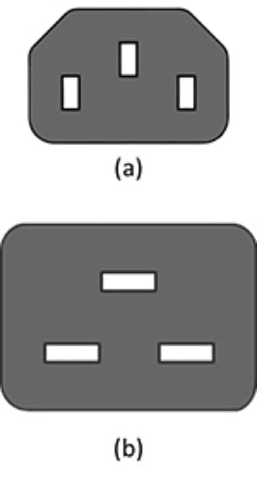
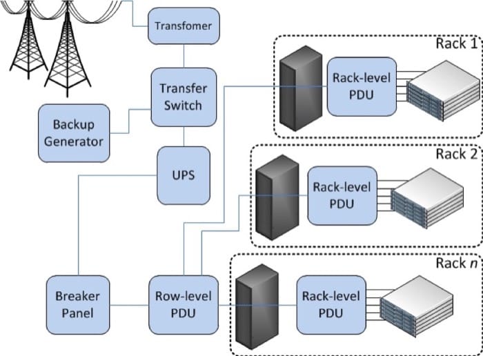
Between the UPS and the IT equipment, there are power distribution units (PDUs). Think of PDUs as similar to power strips you use at home but designed for higher voltages and amps, with more outlets and built-in circuit breakers. They often include monitoring features, so you can remotely see the power draw per branch (group of outlets connected to a single breaker). Some also include per-outlet power sensing (POPS) as well as remote ON/OFF switching for each outlet. The outlets for PDUs do not look like the electrical outlets in your house; instead, they are IEC 60320 C13 (said "C thirteen") (Figure 2.14(a)) for 10- to 12-amp rating and C19 for 16 to 20 amps (Figure 2.14(b)).
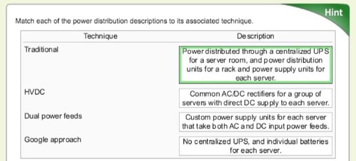
For AC, higher voltage (400V and 480V) is more efficient for distributing power throughout a data center than 240V or 208V but still has to be stepped down before going to the actual server. Most server power supplies are universal and will accept input AC voltages ranging from 110V to 240V. The benefits to running at 208 to 240V versus running at 110 to 125V are slightly higher efficiency (5% to 10%) as well as getting the full rated power output (as labeled on the PSU). Most server room/data center installations will run at 200+ VAC for the efficiency, as well as lower pricing for electrical wiring (smaller gauge copper). In order to boost efficiency, some server PSUs also support 277V directly. Instead of traditional wire, some server rooms employ bus bars that mount over head (above the racks) and have circuit breaker whips that can attach at any horizontal location (these are like track lighting, only larger).
Figure 2.14: Diagrams of the (a)C13 power connector and (b)C19 power connector (Source). Some vendors offer DC distribution, in which the AC-to-DC conversion is done per rack, per row, or per bay, rather than converting AC to DC within every server power supply. These systems have been measured to be more efficient than their AC counterparts, but only 2% to 4% for average loads. [1] Because DC power supplies are not a commodity, these are only suited for large-scale deployments with custom components.
Cooling
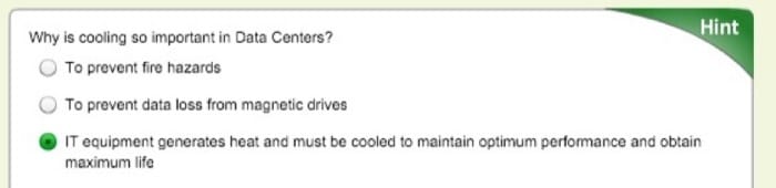
Many of the advances in data center efficiency over the last 10 years have come from new designs and methods for cooling.
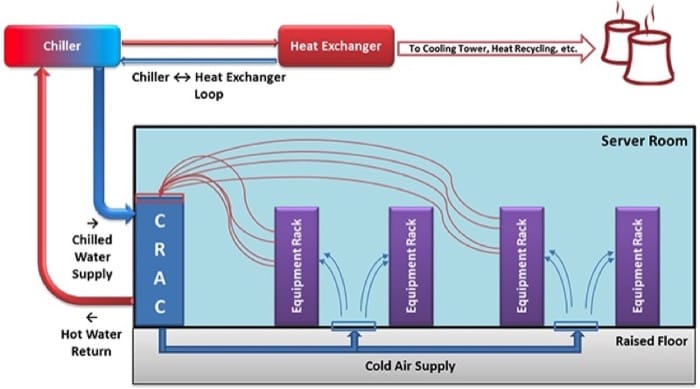
Commonly found in traditional server rooms are computer room air conditioners (CRAC or CAC). These continuously take in hot air and output cold air into the space under a raised floor or into ducts. The difference between a CRAC and a regular air conditioner is that CRACs also provide humidity control. Keeping a relative humidity around 40% is recommended. If the air is too wet, you get condensation (bad for electronics and anything metal), or if it is too dry, you get a higher risk of ESD, or electrostatic discharge (also harmful to electronics). The units' fans have to be sized large enough to create positive pressure and airflow for the volume of the room and have sufficient cooling capacity to maintain the desired "cold-aisle" air temperature (more on hot and cold aisles below and in the next module). The CRACs remove heat through the use of a condenser (similar to what is in your refrigerator at home) or through a heat exchanger that uses chilled water supplied by chillers elsewhere on site.
Measurement of energy for electronics is usually in kW, but most HVAC equipment is measured in tons or BTU/h, so here are some conversions:
- 1 kW = 3412 Btu/h
- 1 ton = 12,000 Btu/h
Did you know? A BTU, or British thermal unit, is the amount of energy needed to heat 1 pound of water to 1°F, and a ton is the heat absorbed by melting 1 ton of ice in 24 hours.
Using vapor compression, chillers remove heat from water in a closed-loop, high-pressure system, usually outputting water that is approximately 42°F (5.5°C). Chillers themselves need to dissipate the heat they remove from the water, which can be through air cooling (fans) or water cooling (needs another water source and/or cooling tower). Chillers are sized based on water temperatures (entering and leaving) and flow rate (gallons per minute). The main sources of energy consumption in a chiller are the electric motors in the compressor and pump(s).
To reduce the load on these chillers, evaporative cooling techniques are now frequently deployed for large data center installations. When hot dry air passes over water, some of the water evaporates, absorbing energy and cooling the air. If you want to use evaporative cooling, it is a good idea to locate a new data center near an abundant water source.
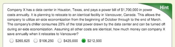
The overall system can be made more efficient if it does not have to cool as much air. Air-side economization is a method of using or mixing outside air when it is cooler than the recirculated air. This method is cost effective in cold climates but not as useful in hot and humid regions.
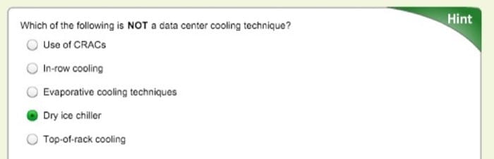
When rack densities increase to 10kW or higher, it is helpful to move the cooling equipment closer to the rack. A product category that allows this is in-row cooling. This way the cold air can flow directly into the front of the IT equipment, and the hot exhaust air from the rear of the rack goes directly into the adjacent air conditioner. This method puts a focus back on cooling the racks, instead of cooling the room. Similar to in-row cooling, there are top-of-rack cooling systems. These systems are bolted to the top of each rack and provide localized cooling on a per-rack basis. The advantage of top of rack is you are not taking up floor space in the server room, while the disadvantage is higher difficulty for installation and maintenance. Smaller capacity, in-row systems use a compressor, whereas higher capacity models use chilled-water or external gas refrigerant. Top-of-rack systems typically use external refrigerant. The advantage of using a gas refrigerant is that there is no chance of water leaking near the IT equipment, but the disadvantage is the added cost of additional equipment in the server room, which removes the heat from the refrigerant loop (using chilled water). Both in-row and top-of-aisle systems offer a modular cooling approach. As long as the facility's chilled-water plant has enough capacity, you can add coolers only when you add new IT equipment, thus staggering your capital expenditures.
Hot-aisle containment refers to a method of placing your racks into rows/bays such that adjacent rows face away from each other (i.e., cold-hot-cold) and then completely enclosing the hot aisle. This arrangement prevents hot and cold air mixing before it recirculates back through the air conditioner, which greatly improves efficiency. Some server room designs employ the opposite, cold-aisle containment, in which the room itself is hot, but the separate cold air is fed into the contained fronts of racks.
Although it has been mainstream amongst overclocking enthusiasts for years, water-cooling products (or glycol or other liquid) are also becoming available from several vendors. There are two approaches: one is to have specialized rack doors that are in essence huge heatsinks, with cold water fed in and hot water returned; the second is to have cold-in and hot-out water hoses going to every server in the rack, and inside each server are specialized heatsinks for the CPU (and GPU) that the water circulates through. In both cases, the servers still require fans to cool the other components (e.g., RAM, hard drives).
One vendor even offers an extreme liquid cooling technique. The (sealed) rack is turned sideways and filled with mineral oil (nonconductive dielectric), and the servers are fully submersed vertically. The fans are removed, and the hard drives have to be sealed (or use SSD). It is best to use servers with front-facing I/O ports.
Many modern buildings' HVAC systems are designed to reclaim heat that is produced in the server room and use it elsewhere, such as hot water or heating (in cold climates), thus reducing overall energy costs.
Safety
In addition to the safety notes mentioned earlier, there are some features of a data center that are safety specific.
Fire Suppression
The preferred system for putting out fires in a server room is to use a clean agent. These agents are stored and transported under high pressure so that it is a liquid and takes up less space. When activated, they are a gas that comes out of misting nozzles in the ceiling. The "clean" term means they do not leave residue or require cleanup as do handheld fire extinguishers (dry chemical) or water sprinkler systems.
Halon was the most popular fire suppressant in this category, but it is a CFC (greenhouse gas), and manufacturing of Halons was banned in 1994. The old systems still exist (must use recycled Halon) but cannot be used in new installations.
A popular clean agent of today is DuPont's FM-200 (CF3CHFCF3), which is nontoxic, and with a properly designed system, the gas will fill the room and extinguish all fires within 10 seconds (hint: do not leave the doors open). It is safe for humans to breath but can create fumes when it reacts with fire. Standard practice is to leave the room (sealed) for 10 minutes to ensure all fire is out.
Another method of fire suppression is the use of inert gases, such as CO2. These gases work by reducing the ratio of oxygen in the air. The problem with these systems is that they are dangerous to humans and also not as effective (depending on type of fire).
Traditional sprinkler systems use a large amount of water to decrease combustibility of everything in the room. They are not as effective for electrical fires, damage electronics, and require extensive cleanup. Sometimes they are required to be in every room by the municipality, so you might still find sprinklers alongside an FM-200 system. With a wet-pipe system, water is already in the sprinkler pipes, and heat from the fire melts the caps and releases the water. A more appropriate dry-pipe system has normally empty pipes, and smoke detectors will electronically trigger a preaction valve to fill the pipes (but the caps still have to melt before water comes out). The main purpose of sprinklers is to protect the building from collapse, not to protect the electronics in the room.
No matter what system is in place, modern facilities have electronic sensors throughout for monitoring and alerting building engineers, security, the fire department, and other pertinent parties in an automated fashion.
OSHA Compliance
Occupational Safety and Health Administration (OSHA) is a governmental entity (under the U.S. Department of Labor) that is tasked with providing regulations to maintain a safe workplace environment. Some of the rules you might find in a data center are not as common elsewhere.
Noise is becoming more of a problem, not just from fans on the IT equipment, but also on the HVAC systems. To maintain safe volumes, ear plugs or ear muffs are recommended for all personnel while inside the server room.
Procedures for removing floor tiles on raised floors should include cones or temporary barriers so that someone does not accidentally fall through an open hole. If the subfloor is deep or is superficial, workers should be harnessed, and the tiles should be tethered before removal.
Electrical safety is relevant because of the large amount of high-voltage circuits found in modern data centers. Any electrical maintenance or installations should be done by certified electricians. Large UPS cabinets have a potential for lethal electrical arcs, so arc-flash ("bunny") suits must be worn during maintenance. All racks/cabinets, PDUs, and other electrical equipment must be properly grounded. An emergency power cutoff (aka "big red button") should be installed, which when pressed will cut all power to the room (or module or bay) if someone is getting shocked.
For server rooms in older buildings, all locations of asbestos should be clearly marked, or technicians should be trained for awareness and the use appropriate safety precautions (respiratory masks) when running network cable (typically to/from other areas of the building).
Servers can be heavy, even 75 lb (35 kg) for a 4U server. Even some large network switches cannot be lifted and must be delivered by forklift. To reduce back strain and risk of injury, you should use teamwork to mount servers. There are also server lifts that can align a server to the appropriate height for installation and removal.
There should be an adequate number of well-marked emergency exits. This seems obvious but is more difficult in large, containerized data centers and where there a multiple floors in the same facility.
References
- The Green Grid (2008). Quantitative Efficiency Analysis of Power Distribution Configuration for Data Centers. www.thegreengrid.org/~/media/WhitePapers/White_Paper_16_-_Quantitative_Efficiency_Analysis_30DEC08.pdf?lang=en.
Geographic Location Criteria
Geographic Location Requirements
For a large multinational corporation, there is a good chance that it already has a number of servers at each of its branch offices and would likely build traditional data centers in the countries in which it is already established. The reason for having equipment closer to the users is for better application responsiveness, which (hopefully) yields higher productivity.
A company whose product is Web based would need to build multiple data centers around the world to provide better service to customers in a wide variety of geographic locations. A common example of this is Web search—Google, Microsoft, and Yahoo! all have large data centers at many sites scattered around the globe. This variety in location provides faster search results to the user, which is a competitive advantage (as long as accuracy is maintained).
A third category of companies that require large data centers are Web hosting providers. They offer server(s) to host the website for companies of various sizes. Small companies might need to have their site hosted in only one location to serve local customers. Large companies might have several different regional sites but would prefer to deal with one hosting company rather than a different one in each region.
An organization in any of the above categories would have similar goals when it comes to picking the location of a new data center. In order to satisfy the facility's needs, it is necessary to locate a data center where there are adequate electrical power suppliers. For the "green" conscious, one might look for an electricity supplier that uses hydroelectric, solar, wind, geothermal, or other renewable energy sources. Regardless of the source of the power, it is desirable to work with a utility company that is willing to negotiate bulk-purchasing agreements, which lock in a specific discounted price per kilowatt hour for several years.
In addition to power, if you want to take advantage of evaporative cooling techniques mentioned earlier in this unit, your data center should be located near an adequate water supply. There are also instances in which you can locate near a lake/reservoir that is naturally cold, use that water as your cold supply, and return it after tempering (lower the temperature by mixing again with cold water from the same source).
For a smaller scale data center, another factor to consider is the cost of real estate and taxes. For a large deployment, however, the cost of the IT and facilities equipment are much higher than the cost of land, and monthly energy costs far outweigh any taxes.
There are also basic logistics that are desirable to have available to support the data center and its life cycle. A supply chain is needed to procure the goods and services, not just servers but all equipment and building materials. There also should be adequate ports/rails/highways to deliver standard shipping containers (40' × 8' × 8'6"; or 12.19m × 2.43m x 2.59m) to your site. Small and medium sized data centers will typically buy servers from companies such as IBM, Dell, or HP, whereas big companies have custom servers, but none of these are manufactured on site and so have to be purchased and delivered. Containerized/modular solutions do more of the manufacturing off site so that installation is faster at the data center. Recycling of raw materials should occur at the end of the life span of the hardware or for failed components, such as hard drives, so recycling availability should also be considered.
Weather
Also mentioned in the previous module was economization, or mixing of colder outside air with the hot air expelled from the IT equipment. In Figure 2.16, you will notice different colored bands. In regions of yellow or orange, you could use outside cooling during the colder seasons, and in regions of green and blue, you could likely use outside cooling year round. Regions marked as red could still use outside cooling but for a few months of the year. For example, because of its cold average climate and renewable energy sources, Iceland has a growing data center industry.
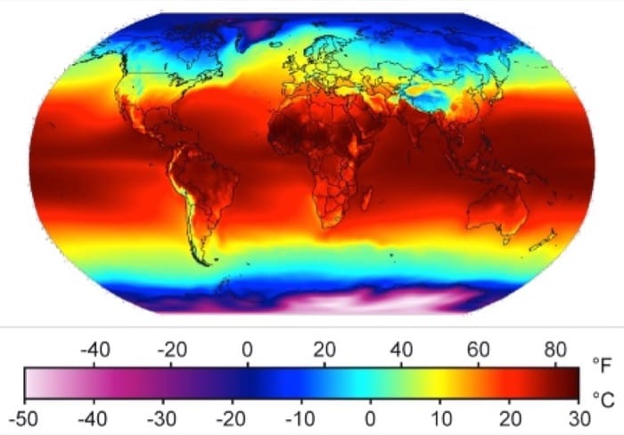
As you will see in the power usage effectiveness (PUE) section later in this module, the energy utilization will be higher during hot months and lower during cold months. This is due to the efficiency gains from "free cooling" (either using air economizers or naturally cold water.)
The average amount of annual rainfall might be a factor if you are considering using rainwater storage/filtration as a water source for cooling your data center. However, the number of sunny days per year in a particular region might convince you to try solar.
Part of a risk assessment for a particular location would include the frequency of natural disasters in the region, such as floods, hurricanes, tornadoes/cyclones, tsunamis, and earthquakes. As you can see in Figure 2.17, different regions have varying levels of susceptibility to a potentially damaging event.
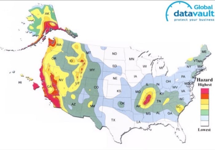
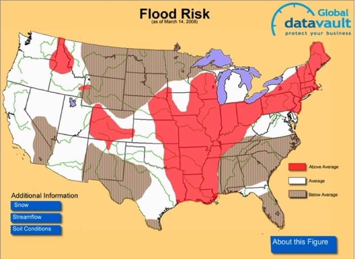
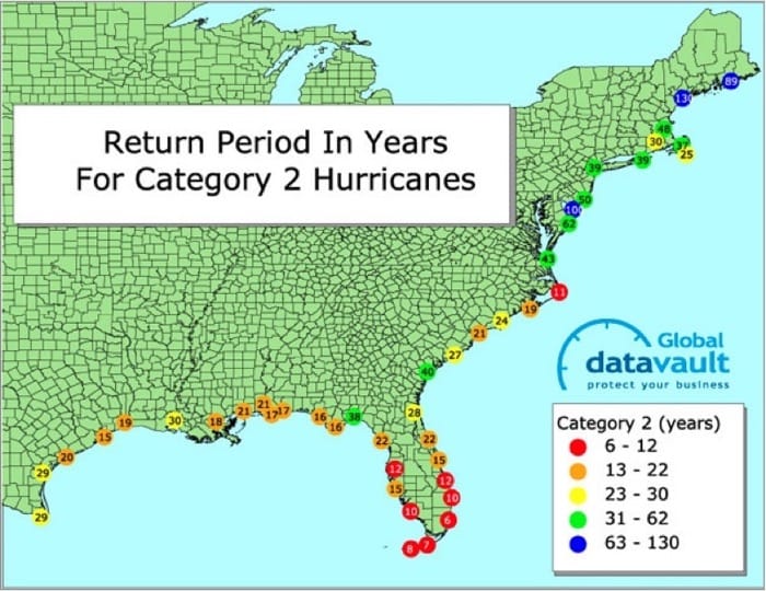

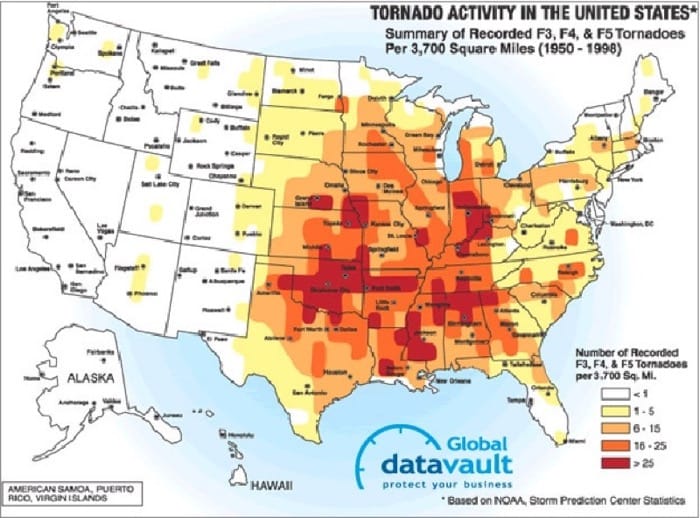
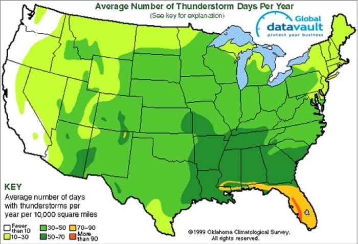
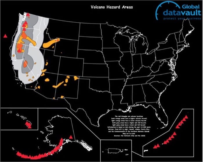
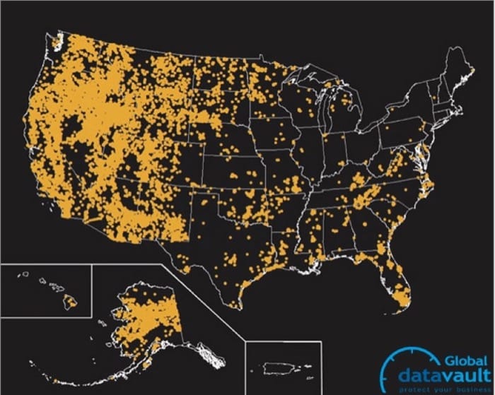
Figure 2.17: Natural disaster threat maps ([Global Datavault](Global Datavault), 2013). (Click on each figure for an enlarged view.)
As a cloud user, or cloud provider, it is beneficial to have two (or more) geographically distinct data centers for your services to mitigate risks of natural disaster, excluding large asteroid impacts, of course.
Connectivity
As broadband adoption among consumers continues to grow, the effectiveness of cloud computing will increase. You can find trending graphs and current broadband adoption at Akamai.
The Internet relies on fiber optics to send and receive data over long distances. Figure 2.18 shows the relationship between multiple tiers of the Internet, in which tier 1 providers own the actual fiber cables, the network equipment, and the buildings they are housed in; tier 2 providers own large networks as well and peer with (have connections to) other tier 2 providers but also have to lease some connections from tier 1 providers in order to reach the whole Internet; and tier 3 providers are only resellers, which provide connections to end users. A single corporate entity, such as Verizon in the United States, may provide services at all tiers.
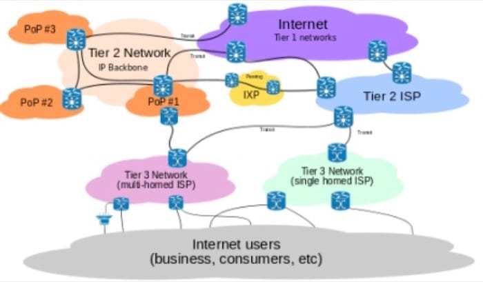
In order to support a large amount of users, a cloud provider should choose a data center location that is in a city/region that has a tier 2 or tier 1 provider. This will also decrease the latency to global users due to fewer hops (each router is a hop) between the client and the server. A data center's requirement for uplink to the Internet ranges from a few megabits per second to several hundred gigabits per second, and that much bandwidth simply is not yet available everywhere.
Costs
Data Center Costs
As you may recall from Unit 1, organizations have to deal with capital expenses and operating expenses for their IT projects. For new companies with an anticipated need for many servers, or for existing companies that have outgrown their existing infrastructure, a decision must be made to build a new data center, expand existing facilities, or migrate some (or all) of their IT services to a cloud provider. With rising energy costs, companies with existing (but outdated) data centers would also consider building a new data center or retrofitting the existing one with new power/cooling. Many scenarios, such a retrofit, might cause unacceptable downtime, so they would instead choose to go to a new location and migrate servers/services from the old location to a new data center. In any of the above scenarios, a detailed cost analysis would be helpful in making the decision (and likely required before any budgetary approvals).
Prices fluctuate often. What was valid in 2011 might not be valid in 2014. The intent of this section is not to give you the tools to do an entire cost analysis on your own but rather to help you understand the types of expenses that go into building a data center.
Capital Expenditures (CapEx)
Capital expenses (which occur only once) for data centers include upfront planning, cost of property and/or construction, facilities equipment (power, HVAC, safety, and security), as well as IT equipment (servers, network switches, initial network connectivity). A more detailed explanation of each follows:
Upfront planning: Upfront planning design costs account for a significant portion of CapEx. This typically includes feasibility and impact studies, architectural design, engineering design, project management costs, and contingency costs. A recent Forrester research study [1] estimates these costs to range from 20% to 25% of the total cost for a typical data center.
Property costs: A principal expense incurred in building data centers is the cost of property. This, of course, varies significantly depending on location. Organizations typically have the option of either constructing a building from scratch or to repurpose an existing building to be a data center.
When building from scratch, many costs, such as the real estate transaction, consultant, brokerage, and building permits, apply in addition to the actual cost of building the data center "shell," which could include excavation, grading, roadways, utility connections, and physical security. Reed Construction Data has estimates for the United States and are typically between $200 to $300 per square foot, depending on the type of building and labor.
Many organizations opt to repurpose existing buildings, particularly those that have been abandoned, such as factories or mills, among others. Google's Hamina data center in Finland was repurposed from an old paper mill. Barcelona Supercomputing Center is an example of an old chapel repurposed as a data center site.
Leasing a building or subleasing space in a building can also be done, shifting this capital expense to an operating expense.
Facilities equipment: Some heavy equipment is often installed during the construction phase, and once the building shell is complete, data center–specific facilities can be built, and equipment needs to be procured and commissioned. This includes most of the equipment outlined in the "Facilities" page in the "Data Center Components" module, such as cooling (CRACs, chillers, condensers, water tanks), electrical equipment (power distribution, generators, transformers, UPSs, automated transfer switch), and fire detection and suppression systems (FM-200).
Estimates for the cost of HVAC and electrical equipment are approximately 20,000 per kilowatt of IT load. [1] In addition, fire suppression systems costs can range from $20,000 to $60,000 for a typical data center spanning several thousand square feet.
IT equipment and connectivity: Once the data center facility is ready, equipment can be moved in and installed. Typically, this involves purchasing rack-mountable servers and networking and rack power distribution equipment. In larger data center environments, it is becoming increasingly popular to roll out fully containerized servers with integrated power, cooling, and network management. IT equipment costs can vary widely depending on the size and configuration of the hardware.
In addition to IT equipment, the data center needs to have a dedicated network connection in order for it to be accessible to the organization that is using it. Network service providers typically charge an upfront average of $10,000/mile to install and commission fiber to a data center. [1]
Operating Expenditures
Operational expenditures (periodically recurring) for data centers typically include electrical power, staffing, cooling/HVAC, Internet uplink, maintenance, taxes, and/or leasing.
One of the biggest operational expenses in running a data center is the power, and it can account for approximately 70% to 80% of the overall cost of running a data center. [1] Electrical utility charges to industrial sectors (which differs from residential pricing) can vary significantly from state to state and country to country. In the United States, the Energy Information Administration (EIA), an entity within the U.S. Department of Energy, publishes regular reports on power costs broken down by state and sector. The International Energy Agency (IEA) publishes energy data for other countries as well. It is also important to note that the cost of power has been rising over the past few years. [2] Because power forms a large percentage of operational expenses and total cost of ownership (TCO), large data centers tend to be placed in regions with cheaper sources of power, whenever possible.
Staffing: Even though data centers can house thousands of servers, they are relatively efficient in terms of number of personnel per server. However, data centers still need a number of operational staff such, as twenty-four seven security and an on-site engineering staff. In countries in which labor is expensive, this cost will end up being the second-largest recurring expense after power. These costs can run into hundreds of thousands of dollars per year, depending on the location and staffing levels.
Cooling: Cooling costs also amount to a significant portion of data center expenses. According to a study by the American Society of Heating, Refrigerating, and Air Conditioning Engineers (ASHRAE), data center cooling consumes 42% of the total power drawn by traditional, inefficient data centers. [3] Many organizations are now paying attention to new techniques to reduce the amount of power required to keep a data center cool. ASHRAE has also published thermal guidelines for data center designers to plan and correctly configure cooling systems to maximize efficiency.
Connectivity: In addition to upfront installation and commissioning costs, network connectivity is usually charged monthly or quarterly from a service provider. The fee is typically in the range of several hundred or thousand dollars per month, based on the bandwidth and reliability guarantees of the connection. [1]
Maintenance: Purpose-built data centers also incur significant maintenance overheads in order to keep the facility running smoothly and to minimize downtime. This cost could be 3% to 5% of the initial construction costs. [1] In addition, facilities equipment may need periodic replacement or repair. For example, UPS batteries are replaced once in 5 years, on average.
Taxes and/or leasing: Building permits are required when building new data center shells or if an existing building's structure is altered significantly. Organizations also need to pay some form of annual property tax on the property owned. This cost, like others, can vary considerably from region to region. Average taxes are estimated to be $70 per square foot in the United States. [1] If you are leasing a property, many of these taxes are included in the monthly price of your lease.
Reference
- Rachel Dines, et al. (2011). "Build or Buy? The Economics of Data Center Facilities." Forrester Research.
- U.S. Energy Information Administration. (May 7, 2014). Annual Energy Outlook 2014. http://www.eia.gov/electricity/.
- Barroso, Luiz André, and Hölzle, Urs. (2009). The Datacenter as a Computer: An Introduction to the Design of Warehouse-Scale Machines. Morgan & Claypool Publishers. http://bnrg.eecs.berkeley.edu/~randy/Courses/CS294.F09/wharehousesizedcomputers.pdf.
Power and Efficiency
Server Utilization
As you recall from the introduction unit, multiple servers are virtualized and consolidated onto fewer physical hosts to increase utilization and decrease energy costs. This improvement is helpful, but the demand for IT-related services in organizations continues to grow, as does the number of Web-based startup companies, which have a higher proportional demand for IT equipment.
Video 2.4: Data center efficency.
To see why server utilization is important, let us discuss power consumption when a server is idle (the CPUs are not doing anything, but the HDDs are spinning, and RAM and I/O devices still consume power) versus when the server is at maximum load (when all CPUs are at 100% utilization).
To estimate the power consumption (P) at a specific utilization (n%) use the following formula:
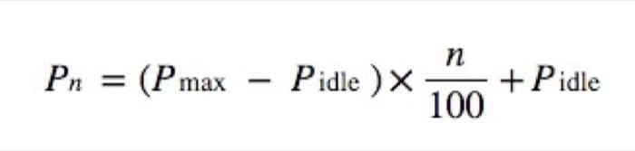
Through empirical measurements, this approximation is accurate to within ±5% across utilization rates.

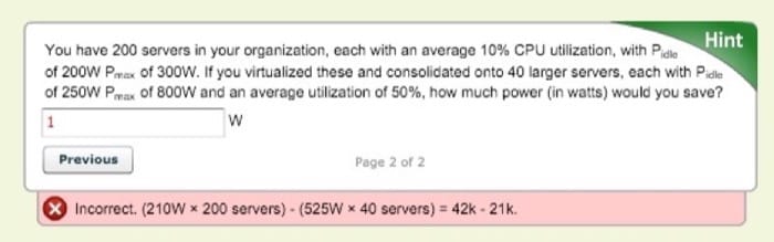
If an organization wants to decrease its overall monthly operating expenses, it has to do so both inside the rack and outside the rack, and to minimize the latter, you must first understand power usage effectiveness (PUE).
Power Usage Effectiveness (PUE)
As we have read earlier, a data center draws a significant amount of power, from kilowatts to several megawatts. The cost of power is a significant element of the operating expenses of a data center and hence contributes to the total cost of ownership (TCO). As companies are offering more Web-based services, which are housed at a data center, the cost of power becomes an important element in the cost of offering services on the Web. Furthermore, some projections claim that data center related emissions will triple by 2020. These economic and environmental factors have accelerated the interest in measuring and improving the energy efficiency of data centers.
The power drawn by a data center is shared between the IT equipment and the support equipment, such as the power distribution and cooling facilities. Data center energy efficiency can be thought of as the ratio of the energy delivered to the IT equipment to the total energy delivered to the data center. Clear and standardized efficiency metrics are needed to help data centers to understand their energy efficiency, identify areas for improvement, and perform comparisons over time.
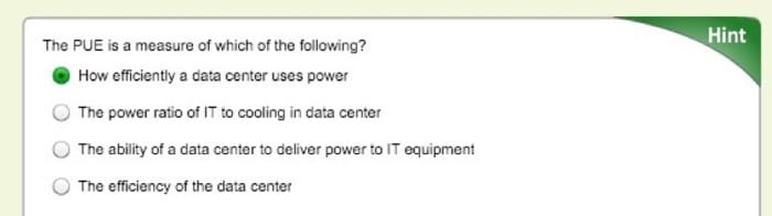
The Green Grid consortium has developed the PUE and its inverse, the data center infrastructure efficiency (DCIE). The PUE is simply the ratio of the total power entering the data center divided by the power used by the IT equipment. PUE measures how efficiently the power is delivered to the IT equipment in the data center.
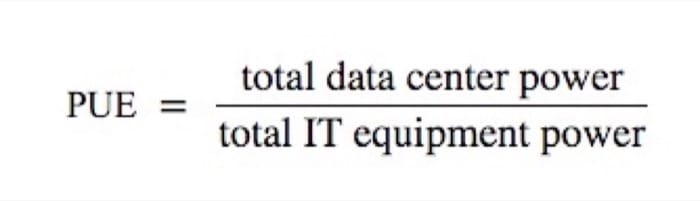
If a data center's PUE is 3.0, then the data center facilities (e.g., power distribution, cooling) utilizes 2 units of energy for every unit delivered to the IT equipment. The lower the PUE, the more efficient the data center facilities. An ideal PUE is 1.0, which would indicate 100% efficiency, meaning that all the power drawn by the data center was delivered to the IT equipment.

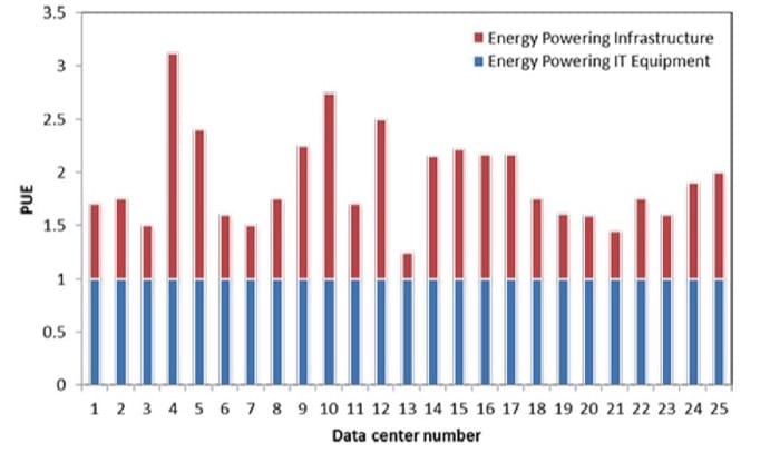
In 2007, the Lawrence Berkeley National Labs (LBNL) ran an energy study for 25 data centers (see Figure 2.19). The best PUE, 1.14, resulted in about 87% of the site energy reaching the IT equipment, while in the worst case (PUE 3.0), only 33% makes it to the IT equipment.
The PUE allows companies to identify areas for improvement, address these areas, and monitor the progress in PUE over time. Google publishes quarterly PUEs for their actual data centers, as shown in Figure 2.20. Because Google's data centers are mostly in the northern hemisphere, the average PUE typically rises in the summer because they require increased use of the cooling equipment.
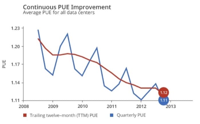
Google improves the efficiency of its data centers using five methods. [1] First, they accurately measure and record the PUE as often as possible. Second, they design good air containment to limit the mixing of hot and cold air. Third, they increase the cold air temperatures because equipment manufacturers allow their equipment to run within aisles at higher temperatures. Fourth, they utilize free cooling whenever possible. This possibility is determined by the geographical location of their data centers and the number of hours per year that allow the use of cool ambient air, evaporating power, and large thermal reservoirs. Fifth, they minimize power distribution losses by eliminating several power conversion steps. The lowest recorded PUE to date at a Google data center is 1.08, which is around 92% efficiency.
PUE simply measures the efficient use of power. Understanding the energy contributors to PUE is important to improve data center design practices. However, PUE is not sufficient as the only measure because it does not account for the load on the IT equipment. If PUE is low, but the IT equipment is not doing useful work, then the data center is losing money. Some recent practices include utilizing a TCO metric that accounts for the cost of the server, which is the total cost of energy that it will consume while running a specific workload over its lifespan. Using this approach, data centers will utilize application-specific optimizations, which will lead to more effective use of the data center equipment.
PDU Branches (Optional Reading)
In an earlier module, you were introduced to a PDU, or power distribution unit. You also learned about inefficiencies related to multiple conversions. This section shows you the advantages of using three-phase power and some common pitfalls to avoid when choosing the size and number of PDUs. This section is optional reading as it goes into specific details concerning electrical engineering
There are several types of power distribution: rack level, row level, and room level. All of them have an input electrical feed and provide one or more branch circuits, with each branch protected by a circuit breaker (a safety device that will "trip" if there is an overload, stopping the flow of electricity). The difference with row-level PDUs is that they typically take a higher voltage and output to a lower voltage using a transformer (transformers generate heat, so you will also find cooling fans inside a row-level PDU).
Three-phase power (often denoted with Greek letter phi [3Φ]) is how AC electricity is generated and transmitted, with each phase a sine wave that is 120 degrees apart. It is not common to have three-phase power in homes, but it is common in industrial buildings and a requirement in any modern data center. It is important to keep each phase as evenly loaded as possible. You should not plug all servers into one branch before going on to the next—stagger them instead. The important thing to know is that the total power that can be handled by a three-phase circuit is greater than that of a single phase (1Φ) for each copper wire (same thickness/gauge).
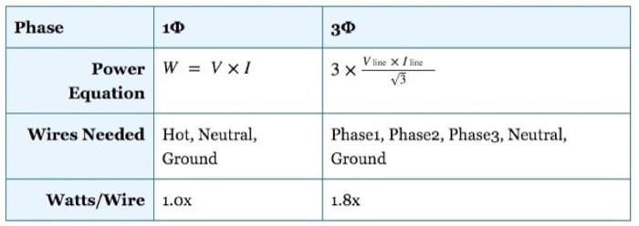
For example, given V = 120 volts and I = 15 amps, then single-phase power = 1800W per three wires; and given Vline = 208 volts and Iline = 15 amps, then three-phase power = 5410W per five wires. (Recall that it is only the current/amps that determines how thick the copper has to be.)
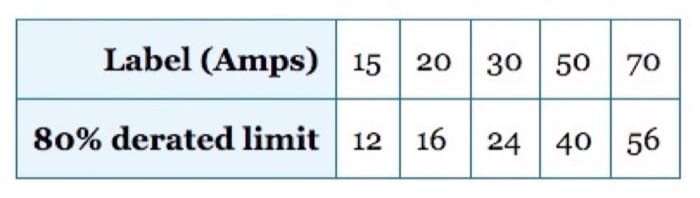
Knowing the maximum power of any branch is important for choosing the number and size of PDU(s) to power your IT equipment. U.S. electric code states that the line current should not exceed 80% of the rating of the breaker (or fuse).
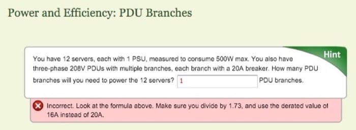
It is rare for a server to actually consume the number of watts that their power supply is rated. For example, a PSU is labeled as 975W, but the server might only consume 650W at maximum capacity. For this reason, it is useful to take power measurements of each new model of server at various loads (idle, 25%, 50%, 75%, 100%) before putting it into production.
When designing a redundant system, it is common to have multiple independent paths from the power source to the IT equipment. You can think of redundant power (and cooling) systems like hard drives in RAID. Recall that in a RAID1 mirror, you withstand a drive failing, but you also lose half your capacity, which is analogous to 2N redundancy—you cannot load a single component (e.g., UPS, generator, PDU) greater than 50% of its original capacity. While in RAID5, you still withstand a single drive failure, but you get higher utilization of individual drives, which is what N+1 redundancy is like for power and HVAC equipment. The remaining (working) units have to absorb the workload of the failed unit.
For example, you have a 100kW load and desire to have redundant UPS. In a 2N system, you have two UPS, each capable of powering 100kW, but their normal load would be 50kW each. If you use three UPS units instead, each could be smaller and capable of handling 50kW each but having a normal load of 33kW. In this case, the utilization is higher (66% instead of 50%), so the UPS would also run more efficiently.
Although blade chassis and some larger 4U/5U servers have N+1 power supplies, most servers and network equipment are designed with 2N redundant power supplies. For this reason, in a traditional data center, you would run two independent power feeds to each rack. This way, if you lose power in one feed, the other can take over. You must be cautious, however, because when one of the two feeds fail, the other one gets double the load. Incorrect assumptions often lead to overloading a branch circuit, which goes unnoticed in normal conditions. Then when there is a single failure, it has a cascading effect, overloading the remaining branches and tripping the breakers. This single failure leads to some or all servers in a rack losing power completely.
Power and Efficiency: Redundancy
You have a 100kW load and are using an N+1 design for UPS, with 3 + 1 = 4 UPS total.

You have 12 servers, each with dual-redundant PSUs, which are measured together to consume a maximum of 500W. You also have two power feeds (A and B) going to the rack. To each feed, a three-phase 208V PDU is attached. Each PDU has three branches (one per phase), each with a 20A breaker.

References
- GoogleEfficiency: How Others Can Do It. http://www.google.com/about/datacenters/efficiency/external/.
Redundancy
Data Center Redundancy
The following video (Video 2.5) covers some important aspects of data center redundancy:
Video 2.5: Data center redundancy.
Data Center Tier Classifications
Data centers can be classified based on reliability. In order to understand the four different tiers, as specified in TIA-942 standard, you must first know what is meant by the word reliable. Reliability is most frequently measured in uptime, or availability. A service that is 100% reliable is extremely difficult to guarantee, and, therefore, no companies will make that claim in their service-level agreement (SLA) to a customer. But if they did, it would be available to users every second of every year.
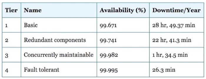
Tier 1 has non-redundant components, such as power, cooling, and network connections, which can lead to downtime for maintenance in addition to single points of failure (SPOFs) (service is disrupted if a single part of the overall system has a problem). Tier 2 still has a single path for power and cooling but adds redundancy, such as UPS and a generator. Tier 3 adds multiple paths for power (multiple UPS and PDUs from the source to the rack) and cooling (e.g., several CRACs feeding raised floors). Tier 3 allows for no interruptions from planned maintenance. Tier 4 is similar to tier 3, but all paths must be redundant and can continue operations at full capacity with at least one unplanned outage (e.g., losing main power or network provider, UPS failure, AC outage).
Even a tier 4 data center could incur downtime due to multiple simultaneous outages, as occurred for Amazon during a large thunderstorm in Virginia. [1]

The percentage of availability can be measured in hours, minutes, or seconds. Downtime is calculated as:

For example, the calculation for the downtime that a tier 4 data center should achieve is as follows:


References
- Malik, Om. (2012). Severe Storms Cause Amazon Web Services Outage. http://gigaom.com/2012/06/29/some-of-amazon-web-services-are-down-again/.
Reliability Metrics
Mean Time Between Failures (MTBF)
Sometimes, when you read material referencing availability and reliability, you will see the term nines used. Five nines or nine nines refers to the number of nines in a percentage of availability. Two nines is 99%, three nines is 99.9%, four is 99.99%, and so on.
You will also see the phrases mean time between failure (MTBF) and mean time to failure (MTTF) in the specifications for many individual components (e.g., hard drives, motherboards, power supplies). These are defined as the average number of hours that component is expected to last and are usually determined by the manufacturer using a sample of parts in more extreme conditions. However, reported failure rates in the field often are higher. For example, hard drives are rated 1 million hours or more, but they have been found to be 2 to 10 times higher, [1] and Google found drive failures rates to be 50% higher on average in their study. [2] The failure rate is 1/MTBF. For example, if the MTBF of a device is 100 hours, then the chances of that device failing in 1 hour is 1/100, 0.01, or 1%.
It is important to note that when determining the overall MTBF of a system that has non-redundant components, the MTBFs of each individual component add as a reciprocal. Formally,

On the other hand, when a system consists of redundant components, required in both components simultaneously to have an overall system failure. The overall MTBF of the system is thus the product of the MTBFs of each individual redundant component of the system. Formally,

Availability and Reliability
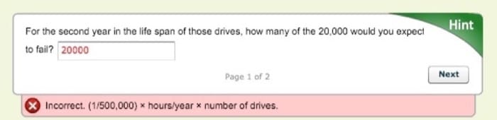
Assume you have 20,000 independent hard drives of a particular model in your data center, each with a manufacturer specified MTBF of 1 million hours. Assume you do not trust the manufacturer-specified MTBF, so divide by two to get 500,000 hours.

One factor that is often overlooked when considering uptime is human error. No matter how much redundancy is designed into the system, even if it is properly implemented and maintained, there is some likelihood of a mistake being made by a person. The result of which eventually leads to a service being unavailable (downtime). Some mistakes can be prevented through policy, specifying standard configurations, good documentation, and change management.
When it comes to large cloud deployments, there is little focus on the hardware resiliency of an individual server. When 10,000 or more servers are working together as part of a single application, the application itself builds in the fault tolerance (more on that in the next unit, "Resource Sharing"). In this situation, a single server failure, or even several, will not disrupt the application/service. Small and medium sized businesses, or even a large enterprise that has legacy applications, cannot afford to author these cloud-style, fully customized applications, so they rely on third-party software, most of which does not respond well to hardware failures. Instead, cloud providers will focus on server hardware that is inexpensive and as energy efficient as possible, removing unneeded parts.
References
- Schroeder, Bianca, and Gibson, Garth A. (2007). Disk Failures in the Real World: What Does an MTTF of 1,000,000 Hours Mean to You?. In Proceedings of the 5th USENIX Conference on File and Storage Technologies. 1–16 Pages.
- Eduardo Pinheiro, Weber, Wolf-Dietrich, and Barroso, Luiz André. (2007). Failure Trends in a Large Disk Drive Population. In Proceedings of the 5th USENIX Conference on File and Storage Technologies.
Summary
- Servers mount into racks, come in incremental heights, called rack units (e.g., 1U, 2U, 3U), and have various depths. Larger cases allow for more expansion and/or redundant components.
- Servers support more CPU sockets and DIMM slots than a desktop or laptop.
- There are many types of PCI express cards available to expand servers, including RAID controllers, network cards (1, 10, or 40 gigabit Ethernet), Infiniband HCAs, storage HBAs, and coprocessors/accelerators, such as GPUs.
- HDDs and SSDs can attach to a host through SATA or SAS and are used as building blocks for larger storage arrays, often employing RAID technology. These arrays can be a directly attached DAS, a remote block device SAN (using FC or iSCSI), or a remote file server NAS (using CIFS or NFS). Distributed file systems use many servers or arrays in parallel to increase performance and resiliency.
- Data center networking topology is often multitier, with the lowest tier switches in the same rack (top of rack) or in the same row (end of row).
- Ethernet remains the de-facto standard for data center networks, is available at a variety of speeds, and works over copper or fibre-optic cables.
- Infiniband is a high-speed interconnect, now popular with HPC, and gaining acceptance in enterprise IT data centers.
- Data centers and server rooms contain racks, raised floors, and cable trays and are designed with strong physical security.
- Power distribution comes from the utility company or a backup generator and typically goes through a UPS, through PDUs, to the rack, and then server level. Some systems improve efficiency by converting AC to DC fewer times and/or decentralizing the UPS.
- Servers are most often cooled through CRACs, which push cold air under a raised floor while taking in hot air and removing the heat through a chilled water loop. That loop is attached to a chiller, which itself removes heat by venting through the air or a secondary loop to a cooling tower. Higher densities/efficiencies can be achieved using in-row cooling with hot-aisle containment. Evaporative cooling is also becoming popular for data centers.
- Safety is important for both equipment and personnel. FM-200 provides fast, safe fire suppression. All metal surfaces should be properly grounded, and safety equipment should be used appropriately.